Table of Contents
The Genboard module can control anything from 1 to 8 fuel injectors individually. It is possible to control up to 16 injectors grouped in pairs.
Before attempting to start the engine it is strongly advised that the flyback connection is checked (see Section 10.1.5, “Testing and Monitoring - TODO” ).
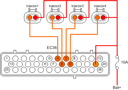
- EC36-pin7 to Injector1
- EC36-pin19 to Injector2
- EC36-pin8 to Injector3
- EC36-pin20 to Injector4
- EC36-pin23 to Injector Common
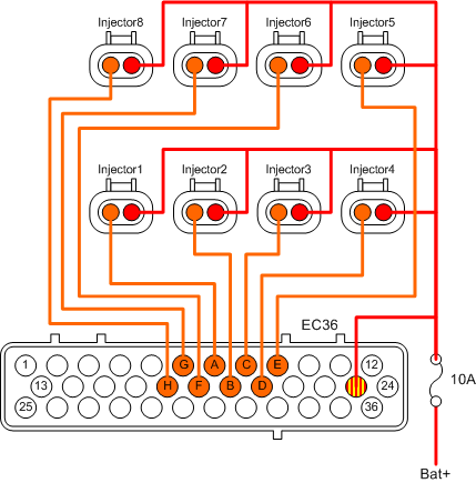
Connecting eight injectors to an 8 cylinder engine is straigth forward.
- EC36-pin7 to Injector1
- EC36-pin19 to Injector2
- EC36-pin8 to Injector3
- EC36-pin20 to Injector4
- EC36-pin9 to Injector5
- EC36-pin18 to Injector6
- EC36-pin6 to Injector7
- EC36-pin17 to Injector8
- EC36-pin23 to Injector Common
The injector common + is connected with a 10A fuse. It is very important that the fuse is connected after the flyback. In case the fuse blows the flyback will still be operational.
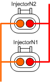
Injectors can be wired in parallel, enabling VEMS to control up to 16 injectors.
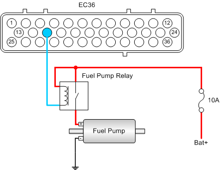
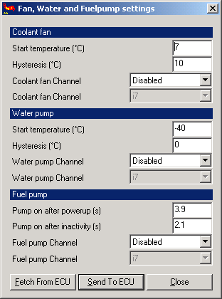
The Genboard module controls the fuel pump relay, which must be wired according to the diagram below.
- EC36-pin15 to fuel relay coil
The maximum load of the control signal is 350mA, if a large fuel pump relay or two relays are going to be used another pin must be used (See Table 3.3, “EC36 connector pinout” ).
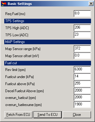
Before configuring any injectors it is important that Required fuel is configured in the dialog 'Basic Settings' dialog (see Figure 10.5, “MegaTune - Injector Settings dialog, required fuel setup” which can be found in the main menu by selecting 'Settings->Basic Settings'.
-
Req Fuel
One of the key values when configuring injectors is 'Req Fuel', short for Required Fuel. Required Fuel is an expression describing for how long the injectors must stay open (in miliseconds) for a single injector pulse to obtain the stoichiometric air to fuel mixture at 100% volumetric efficiency. Before 'Req Fuel' can be calculated a couple of values must be know about the engine.
- I = Injector flowrate [cc/min]
- D = Engine displacement [cc]
- N = Number of injectors
Calculating the required fuel is straight forward using the formula below:
Required Fuel = 6.49 * (D / N / I)
Example #1:
850cc/min injectors on a 2.0L engine.
Required Fuel = 6.49 * (1998 / 4 / 850) = 3.81 = 3.8ms
Example #2:
280cc/min injectors on a 1.6L engine.
Required Fuel = 6.49 * (1597 / 4 / 280) = 9.25 = 9.3ms
Flyback is a very important part of the injector setup, it protects the Genboard module from being damaged by the injectors. Before trying to start the engine, it is a very good idea to test the flyback connection. If the flyback connection hasn't been connected properly internally and externally it most likely will damage the Genboard module.
The first test must be performed to ensure that the internal flyback connection is in place and working.
- Make sure the Genboard module is powered off.
- Disconnect the first injector.
- Connect DVM negative/common to injector connector common pin (the wire that runs to EC36-pin23).
- Connect DVM positive to the other injector connector pin.
- Measure voltage drop with DVM (in diode mode).
The measured voltage drop should be approximatly 600-1500mV. Repeat the test for the other injectors.
The second test ensures that the resistance of the injectors are sane.
- Make sure the Genboard module is powered off.
- Disconnect the EC36 connector.
- Make sure all injectors are connected.
- Measure the resistance between injector common EC36-pin23 and the first injector output EC36-pin7 (use DVM 0-200 ohm scale).
The measured resistance should be between 2-20 ohm. Repeat the test for the other injectors.
Fuel injectors flow a lot of fuel in a very short time, in some cases it is a good idea to test the setup by attaching LEDs instead of the actual injectors. With LEDs attached it is possible to spin the engine, and see if the injectors are activated. TODO LED + resisitor?