Table of Contents
The Genboard v3 ECU is an affordable programmable controller that can be used for multiple applications. The primary and most popular use of the Genboard is for Electronic Fuel Injection on internal combustion engines. The goal of this manual is to explain what is involved in using the Genboard for use in an EFI system and to lead you through the construction, installation, programming, and tuning in this application.
The Versatile Engine Management Systems (VEMS) website is a vehicle for the research, design, and implementation of engine solutions that target performance, reliability, low cost, and versatility. It is also a vehicle of self-learning and fun.
While there is a large network of resources and people for helping you with the Genboard use, you are ultimately responsible for any errors, problems, and subsequent damage that may occur to any engine running on Genboard. You must read and understand this manual before starting your Genboard project so that you may understand what is involved to successfully complete your Genboard installation. Without first reading the wiki and this manual, you will almost certainly become frustrated and fail in your installation or tuning.
Genboard v3 ECU Features
- Support for most common trigger arrangements.
- 1-8 cylinder full sequential injection with coil on plug/coil near plug, wasted spark, or 1-2 distributors. Or, 10-16 cylinder semi-sequential with wasted-spark/1-2 distributors.
- Wide open throttle, closed loop Lambda (AFR) control, mappable through entire loadsite range (pressure, RPM)
- Self learning VE table
- 2 channel acoustic knock sensing. Ignition can be configured to adapt automatically by an adjustable reference table
- Integrated, fully mappable, digitally controlled boost controller
- 2 channel exhaust gas temperature (EGT)
- Advanced idle control using bipolar stepper (ON/OFF or PWM) solenoid and ignition advance/cut for fine adjustments. Together with precise wideband oxygen sensing this results in awesome idle quality when tuned properly.
Genboard ECM and firmware features a very precise and fast internal digital WBO2 controller that can be used for EGO correction in the full operating range, as well as wide open throttle (WOT). The Lambda (AFR) target table is fully mappable (8x8 or 12x12); in practice, tuning to the Lambda target is much easier, more precise and faster than raw VE that is required for simpler ECMs (95% on the market, and 100% below 1500 Euro). With the help of Lambda-target the VE can be automatically calculated and stored.
Genboard v3 Resources and Specifications
MCU: AtMega128
Outputs
- 8 ignition drivers that can directly trigger ignition coils (max 16 cylinders with wasted spark). These can also drive other devices.
- 8 injector drivers supporting pulsewidth-modulated injectors or other devices.
- 2 miscellaneous outputs. These drivers, as well as the 8 injector drivers can be configured as high current drivers for pulsewidth-modulated (PWM) or on/off idle solenoid, nitrous oxide injector, variable intake actuator, etc.
- 1 Idle stepper driver. Can be used as four individual push-pull drivers.
- 8 miscellaneous low current protected open collector drivers for fuel pump relay, idle solenoids, etc.
Communication
- 2 RS232 ports
- 1 1-wire communications port (replaces one RS232) for very convenient anti-theft (see Button Immobilizer) support
- 1 onboard LCD support
- 1 onboard PS/2 keyboard controller
- Feature connector for CAN bus and MMC (multimedia card) add-on boards
- Fast serial boot-loader for firmware updates
Inputs
- 2 variable reluctance/Hall sensor inputs
- 2 knock sensor inputs with advanced DSP based signal processing
- Manifold absolute pressure sensor (MAP) with high precision analog to digital conversion. The use of 2048 signal levels gives noticably better performance than the 256 levels often used, especially on turbo engines. As a result, users can achieve smoother idling and more precise tuning. Standard installation places the sensor on-board, but there are other options for external sensors.
- Coolant temperature (CLT)
- Intake air temperature (IAT)
- Throttle position (TPS)
- 2 miscellaneous inputs for resistive sensors, like exhaust back pressure and fuel pressure
- 2 LSU4 wideband oxygen controllers providing fast and precise digital control
- 2 K-Type exhaust gas temperature (EGT)
- Several internal sensor inputs for custom applications
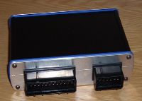
Enclosure and connectors:
- Automotive grade AMP Econoseal III connectors
- Extruded Alubus aluminum enclosure with CNC machined endplates
Versions : v3.0, v3.1, v3.2, v3.3
- v3.0 was the initial release designed 2003 August through 2004 February
- v3.1 minor cosmetic PCB modifications for a bigger series planned 2003.04.13 after the success of v3.0
-
v3.2
- Main regulator exchanged for more available MC33269DT-5 and split supplies (added several other regulators). Higher level of automated assembly, automated bottom side assembly.
- PWMing (low-Z support) automated with 4xMC33151D FET drivers on all boards
- Pads for 2 extra-FETs (DPAK on v3.2)
- Note that 8 IGBT + 10 FETs are still TO220, they were NOT assembled in the automated process (as it is only feasible to do for SMD components). Nothing changes in this respect.
- v3: general name, can be v3.0, v3.1, v3.2, etc.
- v3.3: TODO