Note: it is recommended to split thematically to several pages. (inputs, outputs, other wiring details, issues, etc...)
- Important: Detail your wiring grounding. See GenBoard/Manual/GroundConnections
- Device will get damaged if grounding is not good.
2026-04-24
Introduction:

I have a '72 1300 GT Junior, and mounted a 2000 GTV race engine with 45 Dellortos. Now i'm in the process of installing FAJS ITBs and the following equipment:
Trigger: VR primary using standard 60-2 wheel from Alfa 75 TS and a custom sensor mount:
https://photos.app.goo.gl/N9hCkHMZMPPiGVMNA
HALL Secondary trigger using the distriutor (welded the centrifugal advance shut):
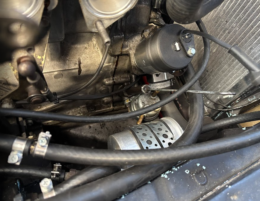
Other sensors are: TPS, IAT, CLT, Map (VEMS module), and one knock sensor (https://photos.app.goo.gl/GVaZPkz6Tbzyhf47A).
The VEMS 3.3 was ordered (by a friend of mine, who didn't use it) like this:
https://photos.app.goo.gl/WZB3iErdmVmpauTG6
Ignition is a standard Bosch ignition module running a motorcraft coil (wasted spark).
This is my wiring list (note the multiple sheets for compartments).
__________
With everything connected, I verified that all sensors except primary trigger was functional.
Problem 1:
VR Sensor is dead.
- If "VR sensor is dead, replace VR sensor". You mean VR input is dead? What is the measured resistance of VR sensor?
Tested one i know works from another car in addition to the brand new one for this car, and the sensors were also verified to the EC36 connector using oscilloscope.
I also connected the VR sensor only i this test setup:
https://photos.app.goo.gl/bzDayVM8pNMGwoHA9
No luck, not one single trigger event in the log. Dead p259?
Reply from support:
- If you disassemble the device (remove endplate first, unclamp the 2 or 3 clamping plates before removing frontplate screws; Be patient, don't damage the insulator-sheet)
- you can measure the +5V supply of p259 (and LM1815) chips. The related regulator also might get warm, indicating current * voltage = dissipated power
- See GenBoard/VerThree/Schematic
- If the LM1815 VCC is less than 0.8V (indicating that likely damaged p259 is shorting it), removing p259 might be a good idea.
- Make a rectangular window from aluminium foil to prevent neighbor components from falling off when heating the p259 chip with hot-air heat-gun
- But first review and fix and document your GenBoard/Manual/GroundConnections
Reply from Per:
Thanks, Will update with findings. I verified ground setup with a DVM earlier, but i'll check with a precision milliohm meter as well.
Measured the new VR sensor to 815ohms, and a older functional one to 650 ohms. Both make voltage when you put metal in front of it.
Update from Per:
Measured 0.4V on P259 VCC - Soldered off P259 VCC - Measured 5V on LM1815 VCC - Soldered P259 VCC back on - Trigger is working!
Mabye i found a short around the pin i took off? Could P259 latch GND to VCC and stay there? Thus me resetting it by taking off VCC pin?
Ground system verified and OK.
Problem 2:
I have the VEMS ignition, fuel pump and coolant fan setup with 9 fuses. fuel pump relay ground is connected to EC36/17 (injector channel) and Coolant fan at EC36/6 (injector channel).
None of these relays actuate in test mode.
Reply from support:
- You can configure for MISC1 or MISC2 output, and change the inverted flag (in outputs dialog) back and forth to test.
- (note: use a "diagonal matrix in injector output groups dialog, so each group contains exactly one injector FET output).
- If there are damaged injector channels, removing or replacing the p259 will NOT fix the problem.
- See [repair/upgrade] if you cannot or do not want to fix it yourself.
- VemsTune: See [vt] Even with newest VT, for new (round or ECU) firmware compatibility, please: Preferences / Update ini files from web. - confirm that you've done Update ini files from web.
Reply from Per:
I did check that the actual injectors worked, and they did. I used the other outputs dialog to test fuel pump and coolant fan, where I assigned the channels and had a test button?
The ini files and firmware are up to date, i can post the versions later.
Update from Per:
VemsTune 1.5.57 - FW 1.2.38 - "no new ini files found" when updating from the web. Still havent found the issue here.
Re-checked that Pin 6/17 is connected to relays ground pin, but does not actuate relays. Suggestions to other more suited channels?
Problem 3 (ignition outputs?): SOLVED
I havent tested much on this yet, but i was unable to get plug spark using test mode. Will look more at this and update.
Reply from support:
- always make sure to have GND return path. But with other problems, it is recommended NOT to try to spark. Use 1k resistor in series with a LED, and test output with that (the anode to +5V, testing 1 switched output at a time).
Reply from Per:
I found a passage about enabling the stepper driver in the user guide - setting water pump channel to S259/7 and start temperature to -40? Mabye that was what was missing?
Update from Per:
That was it - setting up water pump channel did the trick, I now have sparks!