vems 3.7 board vr/vr setup
need changing over to vr/hall
engine m50b25tu
primary trigger 60-2 crank vr trigger
secondary trigger hall sensor on car
i read this page
i am not good at reading the diagram but i can solder and remove bits of a board as long as i can follow instructions
finding it hard to find the followin 2 pics
i have a vr already setup on the ecu as sectrig could u send me the steps to follow
i looked through the input harware page and im not sure if i have to remove the following setup first
v3.3 secondary trigger=VR hardware setup (traditionally the AudiTrigger? setup was used for this, with masking cam-HALL unconnected)
eg
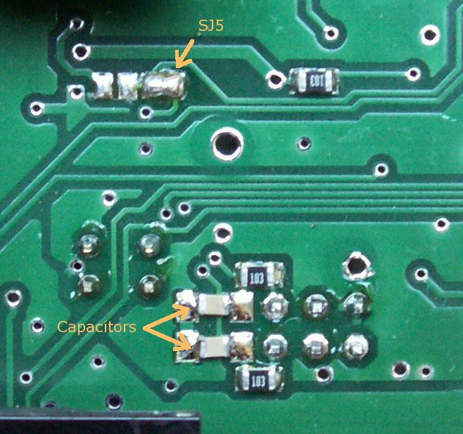
while SJ7 is open, with cam-HALL masking signal unconnected you can measure that R48 (2k7 recommended) pulls up D27 cathode to 3.5V or higher. This is a good verification !
after SJ7 is shorted, unfortunately this cannot be measured (except with scope with input pulses applied)
SJ7 solder-blob on the bottom, so LM1815pin12 output is connected to the microcontroller input pin. This blob is on the bottom, under the FETs.
solder the 2nd LM1815 (same orientation as first: pin1 closest to atmega)
wire from EC18pin12 to the 2nd LM1815 input pad (that goes through a 18k resistor to pin3 of the second LM1815)
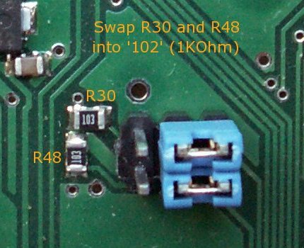
1k pulldown resistor between VR input signal and GND
this is effectively in parallel with the VR sensor. Scratch the green solderprotect a bit at the GND so an SMD resistor can be soldered
To make it work with the 1k VR-input pulldown resistor, connect LM1815 pin5 to +5V with the SJ4 (3pin jumper): solder the mid-pin to the +5V pin that goes LM1815pin8
R182=0 resistor (or short) at LM1815pin7. This helps the adaptive hysteresis (quicker charge). Has the same function as R181 >= 100k for the first LM1815 (soldered in factory) but 0 Ohm (short) is more appropriate here.
optionally increasing the neighboring 220nF capacitor by adding an additional (solder piggyback) +1uF or +2.2uF might be a good idea
i am not sure if the above it pertaining to a hall sensor
this is what ive managed to find but unclear about it if you could provide instruction to first remove the vr setup on secondary trigger. unless it is as simple as just open the sj7 blob and im good. but feel it might be more to it than that. any help would be much appreciated.