Distributor Wiring for MembersPage/MichaelRichards/Projects/NicksGTX
| Distributor Pin | Factory Colour | Signal |
| 1 | Black / Lt Green | GND |
| 2 | White / Red | +12V |
| 3 | White / Brown Spots | Trigger 1 |
| 4 | Yellow / Blue | Trigger 2 |
Trigger setup - trivial modifications, starting from MembersPage/Fero/SUPRA and verified from GenBoard/UnderDevelopment/FirmwareChanges TODO: needs testing (table-test first, with LEDs)
Fero figured out the location of the slots:
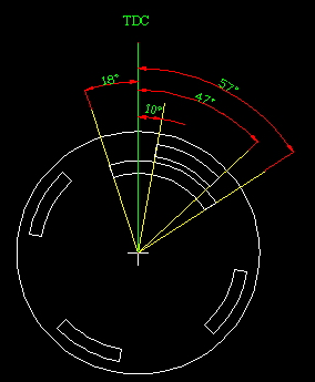
The camwheel rotates counterclockwise.
I've turned this diagram into a graph of the timing versus pulse signals.
As you can see from this diagram the sync pulse rising edge occurs 10 camdegrees after TDC of cylinder 1. I don't see this as a problem because neither the engine nor the ECU care what cylinder is being fired first. This means the falling edge of the first primary pulse occurs 47 camdegrees after TDC1 and 43 cam degrees before TDC3 (next cylinder to fire).
So what if we consider TDC3 the first cylinder of the cycle? The window of 86 crank degrees of possible advance is large enough. The injection and coil firing lines int the h table will just need to be bumped one ahead.
When fed with 12V the trigger2 outputs 5V or 0. Great for the hall trigger setup. Thanks again to Fero.
When the crank trigger is hooked up to the board it measures about
- 3.8V when light passes through the window
- and 150mV when there is an eclipse
I am going to be using fully sequential injection so this makes primary and secondary triggers necessary.
Config Settings:
trigger1, rising,coil,filtering
TODO: are you sure about rising edge?
primary_trigger=07
trigger2, falling, enabled, filtering
TODO: are you sure about falling edge?
secondary_trigger=1C
trigger_tooth=00
another_trigger_tooth=01
tooth_wheel=04
(*16 usec) x crank_minper value=minimum period in usec
Max RPM=8000. So at 8500 RPM, 1crankrot=7ms, 3.5 msec minimum trigger period, 80% of which is: 0xB0
crank_minper=B0 - you can safely set this even lower
The crank trigger occurs 80 degrees before TDC. Fero used 0xA2 which is 81 degrees. I assume this value is adjusted and found with a timing light once the engine is running.
ign_tdcdelay=A0
This is the default value. Interpolation slope, to determine how much is added on top of the 14V value.
ign_dwell6=88
I have no idea what a good ignition crank is for this engine. Fero used 13.25 degrees and so will I for now. (7..10 crankdegrees sounds best unless you know a reason to cheat: eg. because of compression related angular acceleration, compensation might be desirable)
ign_crank_advance=35
180 crankdegrees per tooth, that is 720 (*0.25 degrees) = 0x2D0
tooth_wheel_twidth1=D0
tooth_wheel_twidth2=02 (upper byte)
Engphase modulus. N*tooth_wheel_twidth1 + M * tooth_wheel_twidth2
In our case it should be 4 primary pulses for 720 degrees of revolution.
reset_engphase_after=40 # 0x40==64, since camsync is used
- h[1]=00 03 02 01 .. .. .. .. # reftooth array
- h[2]=20 30 20 30 .. .. .. .. # assuming ignch2 and ignch3 are used in wasted spark setup
These "edge-phase" are not currently used: set h[2] according to relevant h[1]. campulse is not allowed to race crankpulse, so the first crankpulse after the campulse will always be the same predictable cylinder.
cam_sync_f_edge_phase=FF
cam_sync_r_edge_phase=FF