Subpage of V3 general
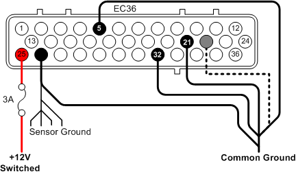
+12V Supply
- EC36-pin25 3A Fused +12v supply
Note
that if you have moved the battery to the rear of the car you may want to run
separate wires for the starter/alternator and for the cars electrical system to
the battery. Otherwise the several meters long cable will cause a significant
voltage drop during cranking that will cause the ECU to reset when the battery
starts to run low. This may prevent the car from starting even if the engine
cranks over.
Once you have
connected and checked the continuity of ground you can connect your VEMS unit to the EC36 plug and apply the power supply. There
is little point in connecting power until the serial connector or LCD screen
has been connected.
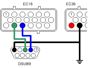
Connecting
serial port
To allow the
connection of the VEMS unit to your PC a serial port
plug must be connected as follows.
- EC18-pin14 to
DSUB9-pin3
- EC18-pin15 to
DSUB9-pin2
- EC36-pin26 to DSUB9-pin5 (GND).
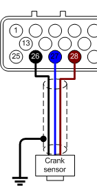
Connecting the
primary trigger (CAS)
Magenetic sensor / Variable reluctance (VR)
Mechanical
considerations (need to be written somewhere and referenced from here)
The VR sensing circuitry is very sensitive to electrical noise,
shielded cable (coax) must be used and good grounding is vital.
- EC36-pin27 VR+ Note that some other ECUs trigger on positive-going edge so their schematic
might mark the + and GND swapped: so don't
blindly follow naming from autodata pinout or some schematic, keep in mind that + and -
might need to be swapped.
- EC36-pin26 VR-
Hall Sensor
VEMS is available configured
for Hall sensors, these are more noise tollerant and
require a +5V supply.
- EC36-pin27 Hall
signal
- EC36-pin26 Ground
- EC36-pin28 +5V
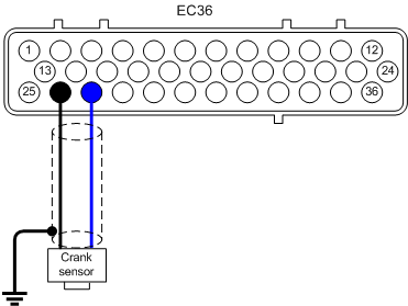
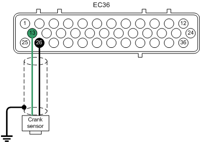
Connecting the
secondary sensor (optional)
Magenetic sensor / Variable reluctance (VR)
With the same considerations with the primary trigger regarding
electrical noise.
- EC36-pin13 VR+ (central wire in coax)
- EC36-pin26 VR- (shield and ground)
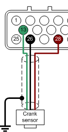
Hall Sensor
- EC36-pin13 Hall
Signal
- EC36-pin26 Ground
- EC36-pin28 +5V
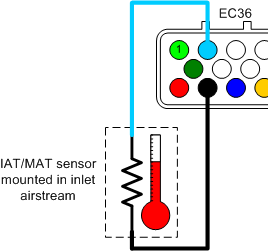
Connecting
the inlet air temp. sensor (IAT)
- EC36-pin2 Signal
- EC36-pin26 Ground
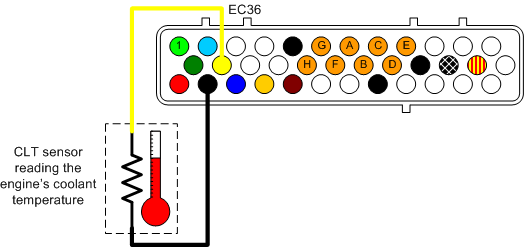
Connecting
the coolant temp. sensor (CLT)
- EC36-pin14 Signal
- EC36-pin26 Ground
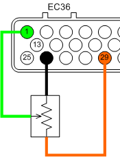
Connecting the
throttle position sensor (TPS)
The throttle
position sensor is used by VEMS to provide fuel
requirements in Alpha-N configuration and acceleration enrichment.
- EC36-pin29 TPS (+5v) out
- EC36-pin1 Wiper out (0-5v)
- EC36-pin26 Ground
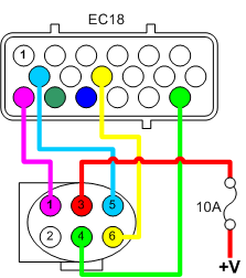
Connecting WBO2 Sensor
- EC18-pin13 to WB6-pin1 (Nerst Cell
Signal)
- EC18-pin7 to WB6-pin5 (WBO2 Pump-)
- EC18-pin18 to WB6-pin4 (WBO2 Heater)
- EC18-pin9 to WB6-pin6 (WBO2 Pump+)
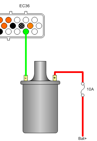
Single coil
In some
instances you will want to keep the distributor, in this case VEMS can be configured to use the original coil as shown.
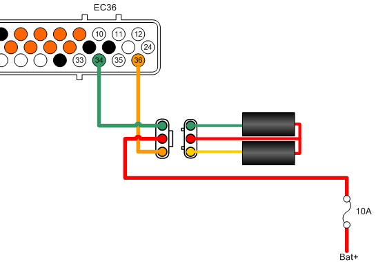
Coil pack
Connecting a
two coil (4 cylinder wasted spark)
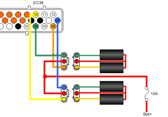
Additional
coil packs, for applications such as 8 cylinder wasted spark
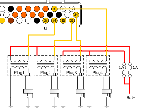
Coil on plug (COP)
Individual
Coil connections are shown, the pins connect to the negative '-' side of the
coil.
Using the
Stepper Motor Driver to control Ignition
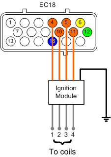
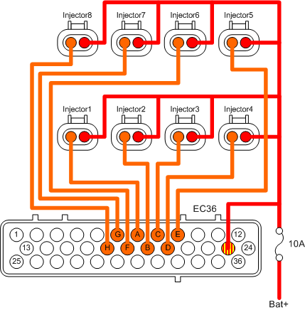
To 8 injectors
are wired as shown here.
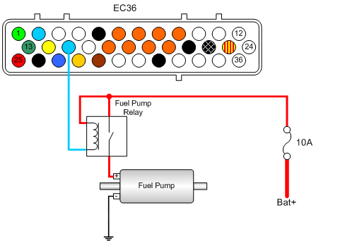
Connecting the
fuel pump
The fuel pump
is controlled via a mechanical relay.
- EC36-pin15 to relay coil
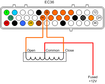
- EC36-pin6 to IAC close pin
- EC36-pin17 to IAC open pin
Stepper Motor IAC
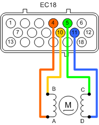
The coils are preferrably connected between A-B and C-D stepper outputs:
- EC18-pin4 Stepper-A
- EC18-pin10 Stepper-B
- EC18-pin5 Stepper-C
- EC18-pin11 Stepper-D
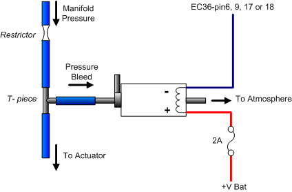
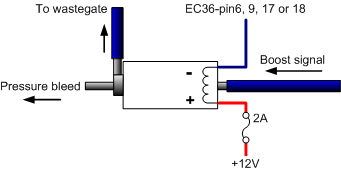
Connecting A Boost Control Solenoid
This assumes
the use of the Webshop 3-port pneumatic solenoid
Connecting the
pneumatic ports
Integral wastegate
actuators
Connection option one
Connection option two
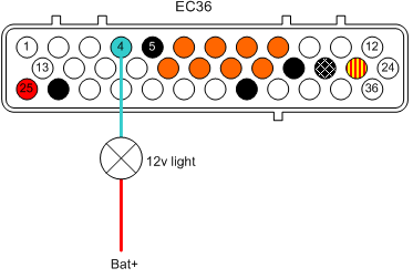
Using Low Current Drivers for a Shift
Light
Connect a 12v
indicator lamp to a switched supply and taking your choice from the table above, connect the lamp's second pin to the VEMS.