Developer's corner
WBO2 hardware lives in GenBoard/VerThree/Schematic.
The WideBand O2 is implemented in the genboard firmware.
PID tuning
There are several types of similar sensors. They might require different PID parameters for optimal operation. Note that even the good-old LSU4 is not finetuned. It's tuned reasonably, and operates well, but verification and finetune wouldn't hurt.
The logs in [LSU4 PID logs] was taken with LSU4 sensor, and slightly improved wbo2 implementation being ported to GenBoard/VerThree soon.
If someone can plot, analize and suggest which seem to be best (eg. lowest fluctuation of the command signals, whatever....), that would be awesome.
Notes useful while developing and auditing wbo2 driver code.
Before wbo2.c read about wbo2 control down this page.
Basics:
- nernst is pulsed: 5V square (128usec + 128 usec), 10k, 220nF
- nernst is amplified
- nernst DC and AC is measured (the AC-measurement part is the most sophisticated and beautiful part of the WideBand). The AC is proportional to nernst internal resistance (Ri), therefore this is named Ri maeasurement
- heater is PID controlled with PWM (as Bosch suggests) to keep the Ri on target. The maximum heater rampup is respected to avoid sensor crack.
- pump (which is a voltage controlled current source) is PID controlled to keep nernst DC on target
- from the pump current the AFR or the O2 content is calculated. Since the sensors are different, a calibration constant is used for this. The calibration constant can be calculated from measuring the RCal resistor in the LSU4 sensor connector housing, or doing a simple free-air calibration. We usually do free-air, and only check RCal to verify if Bosch was precise.
- display the data lcd_display.c
- using for ego control ego.c
- VE learning (ve.c) is based on ego control
Graphs of Mik's wbo2 logs (05/23/2004)
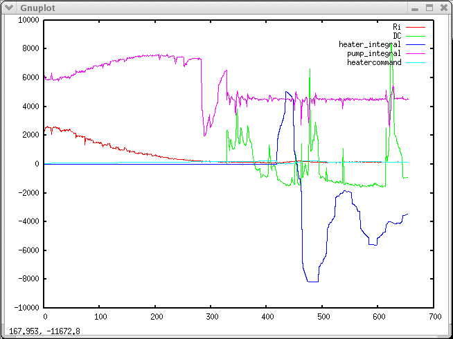
![[Ri]](http://www.vems.hu/files/widebando2/wbo2_Ri.png)
![[DC]](http://www.vems.hu/files/widebando2/wbo2_DC.png)
![[ heater_integral]](http://www.vems.hu/files/widebando2/wbo2_heater_integral.png)
![[pump_integral]](http://www.vems.hu/files/widebando2/wbo2_pump_integral.png)
![[heatercontrol]](http://www.vems.hu/files/widebando2/wbo2_heatercontrol.png)
misc links:
- Bosch LSU Oxygen Sensors
- Bosch 0 258 006 066 LSU Sensor from Tech Edge... $150.00
- Bosch 0 258 007 057, see 1stVWparts.com
- VW part # 021-906-262-B VW Golf GTI 1.8L front-sensor? (note that postage is US$6.95 extra - in the US)
the skipped WBO2 sensor interface chips:
Has anyone seen the Bosch WBO2 interface chip? Its a Bosch "CJ110", in a SO-16L package. It provides the pump current control, pump current sensing, a virtual ground source, a nernst cell reference voltage source, diagnostics, and an offset adjustment control. It needs one A/D port, one input and one output from the host uC, along with the powerstage circuit for the heater. That along with three or four R's and C's will give you a 0 to 9 volt output proportional to 0 to 9% O2.
I have checked the specs for the CJ110 mentioned above. It does not seem to measure Ri, that's vital for an accurate reading and it does not control the heater. It only keep track of the nearst voltage and adjust the pump current accordingly.
There are however two upgraded parts called CJ120 and CJ125. In addition to the features of the CJ110 they also measure Ri and monitor the heater driver. Note that it does not control the heater! The suggested schematic has 21 discretes in addition to the SO24 IC!!!
That's about the same part count as the lambda cirtuit on the Ver 0.1 boards that's on their way now. But about half of the components on the Ver 0.1 boards are there for testing. One of the configurations that will be tested on the Ver 0.1 boards only use eleven discretes and two OP channels.
mail from MembersPage/JorgenKarlsson that boosted the WideBand development on the summer of 2003\n
> Do you have estimations on the LSU4 wbo2 firmware complexity? Is it a
> heater control and an AC pulse + measurement? 400 lines
> for basic wbo2 plus some more for datalogging, inter-uC and calibration?

400 lines are plenty, I think;)
DIY-WB can probably be implemented in 20 lines.
note: wbo2.c is about 1050 lines these days, and the adc sampling lives in adc.c. True, there is a huge amount of comment, and the code is optimized for operation, not linecount.\n
Startup:
Note the the heater must never be heated above 350C before the engine is
running!!! Bosch are very firm on this. Condensation in the tailpipe may
crack the sensor.

The heater has a heatup sequence. We only need to ramp up voltage over the
heater slowly. The ramp are constant at 0.2v/s (max 0.4v/s), but the
starting voltage change with heater temperature. 7.4 volts are acceptable
down to -40C. For 'fast light off' applications 9v are an acceptable
starting voltage at the same temp. But lets say that we start it at 7.4v for
now. Fast light off operation has several restrictions for sensor
installation. Specs are in the datasheet. With my conservative settings the
heater will reach 12v after 23seconds.

Lets use a MaxHeaterVoltage variable, increment that every time we see a
clock overflow somewhere. The main heater control will keep the heater
voltage railed at MaxHeaterVoltage until we reach our temperature goal.

After the warmupphase:

The heater power are controlled to maintain around 8-10 Ohms  over the
heater. This is the main temperature loop. 12volts are max over the sensor
for extended periods of time. 13volts are acceptable for up to 200hours.
It's possible that we don't need to look at the heater resistance at all
when we have the Nearst Ri measurement running.
Yes, it turned out that Ri measurement is important, heater resistance is not interesting.\n
I aim not to use the heater
Ri feedback at all as this will free up one ADC channel and remove the
current measurement resistor.

The heater resistance are available directly as we know voltage and current.
The heater are not pulsed.
The heater is actually pulsed for less dissipation.\n
The heater power will also be controlled by the Nearst cell temperature.
This must have a larger gain then the heater temperature input. This will
probably have to be PID or buzzy logic;) controlled. The thermal frequency
of the sensor are very low (pulsing it with 16volts at 2Hz are acceptable!),
some smarts will probably be needed to get on target quickly.

The Nearst cell temperature are measured by pulsing the nearst cell via a
capacitor and a resistor. The resistor handle current regulation. The
pulsing must be done between 1kHz and 4kHz. Note 2-8kHz interrupt if we
measure all pulses.

In sync with the pulsing the potential of the nearst cell are measured. Very
strong averaging are probably needed. From the differential potential we
calculate Nearst cell resistance and temperature.

I guess that it's possible to have an interrupt every time OC1C switch
state. I haven't checked that yet as there are workarounds if it does not work.
We measure a set of consequtive samples in adc.c. The pulsing period is different than the ADC sampling, but known and considered. \n
The Nearnst cell temperature are also used to compensate the lambda reading
if the temperature are not on target.

The filtered voltage of the Nearst cell (DC: effectively the Ri measurement signal filtered out)
are used to control the pump cell. Simple PID will probably be best.

The resulting commanded pump current are then translated to a lambda value
(lookup). This lambda value are then compensated for actual Nearnst cell
temperature (The compensation factors will probably be a PITA to figure
out.) and forwarded to a simple averaging stage (ten last samples or
something).

It will be very useful to be able to sample the 'average variable' above in
sync with the engine. The same goes for EGT measurements.

I think that the result are then best averaged further before it's stored in
a few variables with different levels of filtering. One easily adjustable
for the external voltage output. One suitable for logger, ecu and bargraph.
A digital display would require yet another filtering.

Well, I think that's about it.

Jörgen