Intake temperature
In a speed density system the ideal solution would be if we could measure the intake air temp when it enters the throttle AND when it enters the combustion chamber at the valve. That is of course impossible, we will have to be satisfied with an average temperature of the air through the intake manifold.
The importance of being able to read the correct intake air temperature at the RIGHT place can't be exagerated. Most installations feature sensors that either sit in the wrong place and read the right temperature or sit in the right place but read the wrong temperature.
One example is a sensor that sit somewhere well before the throttle body and read the right temp there, but as the fuel calculation need the mean temperature of the air when it goes through the intake the read temperature will be too low and an increased intake manifold temperature (greatly dependent on coolant temp, intake air flow and engine compartment temperature) will result in a rich condition.
An other example is that the sensor is in the correct position somewhere in the middle of the intake manifold but it gets heat soaked by the hot intake manifold at low air flows resulting in it reading the temperature of the intake manifold rather then the intake air temp. This often cause a lean condition at low engine loads.
Yet another condition is that the sensor is in the intake manifold, is not heat soaked but is dimmed with fuel that vaporize on the sensor making it read a too cold temperature.
At low loads the air can be heated significantly when traveling through the intake, with some intake designs the intake temperatures can be as high as the coolant temperature at idle!
- Autronic used a "Charge Temp Estimation Table" This table is 3D Value by RPM/Load. The value is a percentage of Coolant Temp blended in with the Air Temp to calculate the estimated Charge Air Temp entering the cylinder. The Math is CLT X Table Value + AIT x Inverse of Table Value)
Example 2: CLT=80, AIT=40, Table Value=75%, Charge Temp=70 degrees. (80 X 75%=60,40 X 25%=10,60+10=70)
Then a fixed correction is applied to the Fuel Pulse Width based on the Charge Temperature. The correction is zero at 15 deg C (Standard Air) and each 2.917 degrees C above or below that is a 1% difference in Fuel Pulse Width.(Or another way to think of this is .34% Fuel change per each 1 degree C)
This table is very difficult to tune, the theory is correct but it assumes a correct air temp from the sensor, which is not always true. If the Fuel Correction could be scaled 0-100% then this method would be far more usable.(Kevin Black)
Requirements
- The sensor has to respond quickly
- The sensor must be isolated from the surrounding material to prevent heat soak
- The sensor must be vibrtion proof to prevent it falling into the engine.
Possible sensor designs:
NTC sensors:
Most engine management systems support only NTC sensors, these are often pretty slow and also tend to heat soak easily because they have to much mass and also need lots of support not to fall apart in the enviroment. The OEM's don't need to worry much about the intake air temp as they use mass air flow sensing, their intake temperature is only of interest for the ignition timing.
Diode:
Autronic use what looks like a small switch diode, the very small mass of the sensor makes it extremely fast and the epoxy filled threaded body isolates the sensor from the manifold.
There are two ways to use a diode, one is to have calibration data for each individual diode in the ecu, or use the diode in a way that ignore dataspread.
By measuring the voltage drop over the diode at two different constant currents you can eliminate the dataspread of the diodes. A snipped from the MAX1153 fact sheet:
Temperature = (VHIGH - VLOW) q/(n k ln(IHIGH/ILOW) (°K)
Where:
VHIGH = sensor diode voltage with high current flowing (IHIGH)
VLOW = sensor diode voltage with low current flowing (ILOW)
q = charge of electron = 1.602. 10-19 Coulombs
k = Boltzman's constant = 1.38. 10-23 J/K
n = ideality factor = 1
MAT/IAT air-temp sensor speed measurements
We measured 3 sensors with hot-air blower and data acuisition system.
One of our partners will develop an extra-fast air-temp sensor that reacts to fast airtemp spikes (only in turbo and supercharged applications or with EGR) with max 1 sec time-constant. Such a sensor is not available today.
We can only post some draft highlights, no exact details. (we don't have everything anyway, it consists of very advanced materials, manufacturing, arrangement, electronics and algorithm we only have partial access to).
Here is a chart, just to have from an old measurements that started the brainstorming on this.
The hot-air-blower was held in hand which resulted in different final-temp, eg. the "Merc" sensor got more heat, and also some variations during the measurement (most significant on the "long" sensor).
The measured sensors had appr. time-constants:
- Long: 4 seconds
- Merc: 5 seconds (one of the fastest commercially available MAT sensor)
- Short: 7 seconds
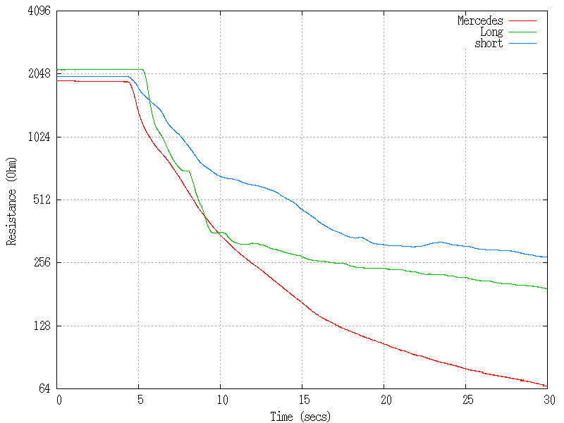
Note the log-scale on the resistance axis. (the difference in Ohm at the bottom is small).
Thermocouple
The by far fastest sensor is the thermocouple, it also offer significant installation advantages. For this application a Type K sensor is suitable as it's the most versatile thermo couple configuration for a car enviroment.
One sensor installation that would have very good performance would be a 1.5mm stainless exhaust temp probe epoxied through a 1/8NPT fitting to protrude 25mm into the intake air stream. Using silicone sealant instead of epoxy could be beneficial for the sensors ability to withstand vibration.
- I wouldn't recommend ordinary silicone sealant as it can't stand gasoline for a long period (don't ask how I know it). Stay with epoxy resin or some oil-proof sealant.