This page is all about the Siamese port problem experienced by the BL A series engine. This is not the only engine to suffer this problem but it is the only one of this design to have been fitted with fuel injection.
With configurable injection end-angle, it's not too hard to add the necessary extras
The real problem is that even an experienced installer is very likely to blow up an engine or two while tuning a siamese port injected engine. Not an issue for a factory, where they sacrifice 20+ engines anyway. But for a home tuner, usually the ECU's reputation suffers. The risks and difficulty of tuning were the primary reasons we decided to not add support to diesels and siamese-injection so far. An application where tweaking results in 30..50% success rate makes reputation worse.
Technically:
- Now that there is Injection angle, and individual injector trim
- introducing perhaps an 8x8 table for individual injector trim replacing the simple curve.
- IE individual injector channel x rpm x trim, thus introducing the RPM element. One row per injector channel and 8 columns for RPM.
This would satisfy the needs of siamease port injection, as long as injection angle curve is still present.
After the dual-camshaft control is tuned with all adjustable-cam engines (Toyota, Mitsubishi,Suzuki,BMW,Audi,Volvo,etc...), we rethink this (either with dual wideband onboard, or with a Vems WBO2 round as a tuning tool). Classic Mini and MG ;)
The A series engine itself had been in production for over 50 years in various capacities and configurations. Rover streatched out its demise by firstly using the single point throttle body injection system, very similar to the Bosch Monojetronic, almost identical infact. This kept the emissions below the limits of the day.
Later developments seen the Multi Point (twin Point) injection system. This is a very clever system that overcomes the siamese port problem of charge stealing. It utilised the Rover MEMS2J ECU used then only on the Rover KV6 series engines with dual lambda and cam sync. This system only ever seen use on the A series and is bespoke to it. Rover patented the siamese port injection design and theories and to date, no other engine has used this system to my knowledge.
It was clear that after 2001 the aging 50 year old A series engine with its siamese inlet ports could not meet the ever tightening emissions standards, that production of the Car, the classic Mini, along with the A series engine ceased.
So taking into consideration that there are thousands of production Minis fitted with the A series engine having siamese ports and fuel injection from 1992 through to 2001, also noting that the Mini tuning scene is getting ever bigger, with more people coming round to fuel injection rther than ripping it out on stiking a carb on it. I feel there is a reasonable demand to address this issue.
History of the a series engine can be found here http://www.austin-rover.co.uk/index.htm?engineaseriesf.htm
The siamese port problem
Firstly some links for some background
There has already been much research and code done for this on the Megasquirt controller, though, the way i see it, is limitted by hardware. Discussion can be found here http://www.turbominis.co.uk/forums/index.php?p=vf&fid=32 here http://www.turbominis.co.uk/forums/index.php?p=vf&fid=33 and here http://www.turbominis.co.uk/forums/index.php?p=vf&fid=29
Most of the work on this so far has been done by Jean Belanger
Courtesy of Dave Coxon (turbodave) of http://www.turbominis.co.uk , is the Rover patent appliction, which to my knowledge, the Mini MPi 1997 onwards, was the only car/ engine to run this system http://www.davecoxon.co.uk/A_SERIES_PATENT.PDF
Marcel Chichak has done an amazing amount of physical testing with the DTA system, his work can be fond here, and is a very interesting read!! http://www.starchak.ca/index.htm#tech
VEMS and the siamese problem
The coding part, although not at the top of the priority list, is not very complex. Actually, there is (commented) code for injection angle, and the y[] table, not used for most setups could be hijacked for injection angle (when boostcontrol is tuned with asymetric PID with simple 20/40/60/80 % loadsite-independent reference position).
The problem is much worse: with siamese ports, the injection angle is very important. It must be tuned for each loadsite to prevent lean mixture in certain cylinders. Also, there is not enough information for tuning (although 4 WBO2-s would be possible to install in an NA manifold). To make it worse, it must be tuned for each injector size (and type).
Tuning is extremely problematic. The question is, if we want to make something that we know could easily result in several blown engines and bad end-user experience. It could be done in 2008Q2 if there are
- at least 30 intended (NA) installs
- at least 20 (NA) for a given injector type
- someone with sufficient experience willing to install 4 WBO2 and do the tuning professionally, for all type of injectors
- I hope noone wants to install turbo with a siamese intake+head ... that would clearly be a recipe for tears
- is there really no bolt-on head+intake (or even complete engine: usually very feasible for an install: the installer often gets it assembled from pieces anyway) that could be an alternative ?
The A Series engine has two inlet ports and three exhaust port so fitting four WBO2 sensors wont work. Also, Im not doubting anything thats been said, but my personal feeling is that it will not be as complictaed to set up as people think. The Mini MPi manifold has two high flow injectors each controlled by two injector drivers, no reason why you couldnt fit four slightly smaller injectors and drive each individualy. Also consider that you only really need to measure WBO2 from the pairs of cylinders, why would the AFR be different, the A series engine could be described as two two cylinder engines, one the mirror image of the other, why would fueling one two cylinder engine be any different than the other, The exhaust ports are paired same as the cylinedrs are on the crank throws, IE #1 and #4 cylinders are at tdc together are paired together on the exhaust. Not taking into account the general inacuracies of any angine.
After seeing the down sides of the SPi wet manifold system, though not unsurmountable, port injection does solve certain problems easily. Yet on the siamese ports it interjects other problems. Its also a bit of a challenge. I can see it working on VEMS fairly easily as the hardware is there, Its just the code! (and tuning!)
Here is the general theory of the siamese code, though not by any means the only one or the right one.
Basics of it are, cylinder pairs 1/2 and 3/4 share the same inlet port (siamese), inlet valve overlap is such that as one valve is starting to close, the other valve is starting to open. The result is, in a port injetion system, as one cylinder is close to the end of drawing on the inlet port, the second cylinder starts to draw on the same port. Getting the right amount of fuel into each cylinder starts to become vague. Rover got round this, 1 suspect, by shifting the injection points for each cylinder into a 'window' of valve opening whereby only one valve is open at any one time
Other thoughts on this are perhaps the injection point is the middle of the calculated pulse width with dual tables firing the injector at different intervals (rather than all at the same point in the cycle). Wiring shows four injection drivers crossed over and commoned up to the two injectors, Mpi Crank trigger shows 4 missing teeth, two 180 degrees apart, ignition points? and the other two 180 degrees apart, but the second having a difference of 10 degrees so in reality 170/190 apart, injection points? Cam sync giving TDC#1 cylinder. In such a way that the pulse width looks as though it is one, you could then alter the pulse width between the tables so that the percieved injection point was shifting yet injection point stays the same(The Rover Mini MPi ECU was developed from the MEMSJ2 ECU used on the KV6 engine. This had dual Lambda and presumebly dual VE tables.) This way with dual Lambda pressent, you can tune the VE tables, rather than have dual active Lambda controlling the correction, so that if the middle cylinders are running rich and the outers lean, you can increase VE on the outer cylinders and reduce VE on the inner cylinders to balance out the AFR. In simple terms you have seperated the middle cylinders from the outer cylinders and given them their own VE tables.
One other thing that can also help reduce this port robbing situation is the use of a scatter pattern cam, reducing port robbing issues, but not eliminating it. One of which already specificaly designed by Kent cams, the MD274SP, for the injection engines with minimal valve over laps for use with Speed/Density metering.
The main problem with the speed denisty air metering is as most will know, large valve overlap cams cause inlet tract pulsing, and this is a major problem with the A series. The kent MD274SP cam is as wild as you can go with speed density on the A series, 246 inlet duration 276 exhaust duration. Not very wild and will give in the region of 100bhp on a 1400cc engine. Nothing special. On a side note, the maximum i have seen from the MPi system is 90bhp< wild cams seriously screw up the sequencial injection strategy. Clearly more room for improvement, the Rover ECU is holding it back!!! Add to that, people are wanting to put a turbo on this system as well!!
Using a programable ECU to replicate the fueling strategy, but use Alpha N and to tune acordingly is the way forward.
There are clearly some major issues with tuning a system like this such as running a pair of cylinders lean. I dont think there is anyone looking at this problem that doesnt already know this and are aware that setting up on the dyno is a must!
I will be honest and say that, i dont think I will be pushing this subject further with VEMS as i am building an 8 port 16v engine, and there is a company taking up the gap in the market http://www.canems.co.uk all I can say is good luck to them, it is still a very complex system to set up. As for turbo charging, you are correct, it is a royal can of worms considering the WBO2 sensors do not like the back pressures experienced before the turbo, where they need to be, lol and some one suggested tunning by EGT with the WBO2 after the turbo. Other suggestions have been put forward such as a bypass line into a chamber with the WBO2 sensors fitted there. To be honest, why go to all that trouble, when you'd be on the road far sooner with a wet manifold set up. Siamese port injection is dead in the water in my eyes.
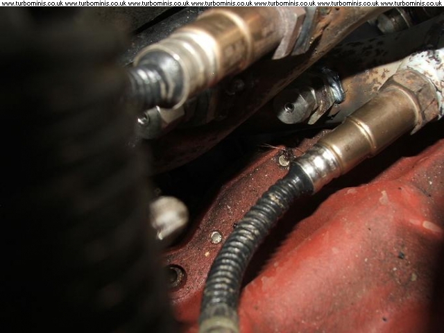
I have recently installed two wideband lambda sensors and EGT thermocouples onto the exhaust manifold of my Mini for some research.
One of the main reason I baught the VEMS was that it 'suposedly' has dual channel wideband. This is some what true, the hardware is there, i was advised that two FETS are required for these, and both are installed. Everything hardware wise is there, fair enough, But where is the code/ firmware?
All i want to do for now is monitor the data from the second wideband channel, nothing else at this stage. It has been said that the outer two cylinders of the A series engine always runs lean on a carb or SPi set up. I find this difficult to understand, how can this be when the charge is evenly distributed as a mixture. I dont believe the outer cylinders to be running lean, but rather at a reduced VE to the inner cylinders as a result of the charge stealing caused by the valve overlap.
I have the hardware, and want the firmware simply to control and monitor the second wideband chanel. Can some one please help by compiling a one off firmware build adding the second wideband channel as a data logging point only.
This is the first stage of development. I am more than willing to spend time on this. I have several people that I can fall back on for some of the tuning aspects of this, but need the tools to do it. Firmware is the key ;)
yes (as 1.0.32+ seem to stabilize), this makes sense anyway. Keep nudging on ChatViaIrc.
I am still interested in the Dual wideband data logging channels.
Back to MembersPage/Sprocket