Field Report
Calibrating Unit No.638
Toyota 4A-GETT, 36-1 crank trigger, wasted spark coil pack. LowZ injectors (6R8 resistors) Transient suppression diode.
System was being configured by a professional calibraition engineer. His verdict was that the ECU was fit for purpose, but needed a few additions to bring it up to a more professional standard. His observations are detailed below. (And added to from an email sent 30/10/2006
Air temp fuel enrichment & ignition retard.
As temperatures increase over 70degC scalable spark and fuel enrichment is required to help decrease the knock window. Spark needs to be retarded as IAT increases, a simple scaling table would be sufficient.
Increasing IAT directly effects the likelyhood of knock, when IAT increased the advance needs to be reduced in order to decrease the likelyhood of knock.
If you assume that the normal operating air temp is 30-50 degC then you'd want to run with a constant enrichment value 30-45, 45-60deg you'd take fuel out because of the drop in air density. 60 up you want to start adding more fuel.
This also applies to coolant temp.
Knock Sensor
Knock sensor values need better explaination. MembersPage/PhatBob will need to work on this, by reading the TPIC8101 datasheet and wording the information in a more user friendly manner.
Accel enrichment
Getting the throttle opening speed values is difficult as even the slightest touch on the pedal maxed out the dv/dt value.
Suggested method:
RPM Vs pulse width adder Vs decay time look-up table - output is pulse width adder and a decay time at that rpm (as trans fuel requirements are as dependant on rpm as pedal movement)
Dv/dtps Vs scalar look-up table. Output is scalar based on rate of change of pedal.
Transient fuel is the output of the first table * the second. This approach works very well.
Boost Controller
Boost control needs more user information, such as display internal variables, most importantly solenoid duty and integral railing.
The air restrictor is needed because the valve simply cannot do it's job without it. Even with fully open valve, the full boost pressure would get to the actuator: the valve (even if fully opened!) could not reduce the actuator pressure without the restrictor (=> so control would be impossible). It's impossible to regulate the actuator pressure if there is no restriction that is a good match to the valve opening (thin tubes might also be sufficient with a rather big valve). See what happens as we go from a highly oversized feed (compared to the solenoid controlled valve's maximum opening) to the right size:
- you can be 100.0000% sure that with a thick air-pressure-supply and a tiny valve you have ABSOLUTELY NO control, even the valve fully opened has no effect on the pressure that gets to the actuator
- with a not-so-thick air-pressure supply the valve has some effect, just not enough to reach target boost
- with an even thinner supply the valve has some effect, even reach target boost, just not enough to reach target fast (that's one method to raise/lower boost without electronics, but it's not as fast as a well configured electronic control)
- with the right size proper regulation is possible, and it can be reached fast (when properly configured)
This assumes the connection using a t-peice to bleed the valve, the setup was connected thus: 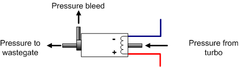 The config, tables, msq and final datalogs are all here: http://www.vems.hu/wiki/index.php?page=MembersPage%2FPhatBob%2FInstallations%2FMattJ
While the Boost controller was configured succssfully the Engineer felt that it was only possible because he'd calibrated boost systems before with the feedback. Please note that the controller WAS Calibrated correctly as it repeatedly held 200kpa (100kp boost) for prolonged periods.
Fuel Trim
Being able to trim injectors to take account of different cylinder charge would be useful (seeing around 20-25C difference between the two turbine inlets on Matts car, could be equalled by richening the appropriate two cylinders)