Corrado g60 turbo
| [Start] | [Questions ] | [ Injector] | [Ignition] | [Triger] | [Display] | [Wbo2] | [Config] | [Table] | [Wiring] | [Idle] | [Tools] |
VW Passat
| [Start] | [Elektronic throttel] |
Audi S2
| [Start] | [Questions ] | [ Injector] | [Ignition] | [Triger] | [Display] | [Wbo2] | [Config] | [Table] | [Wiring] | [Idle] | [Tools] |
10-9-2007
The car is running…
What I did to get the auditrigger to work:
1.Add a 10K resister to GND (pull down) to the sec. Trigger 2
2: Shorted SJ4 lm1815 pin 5 to Vcc 5V
Et seems like the Lm1815 IC worse latch and newer got unlatch therefore it’s pulling down the sec. Trigger.
Trigger tester tests
4-9-2007
- We tested the trig2 (sj7 open) and it seams to work well using *a 100k-resister pull-up to 5V.
- Shorted sj7 and pull-up r48 still ok
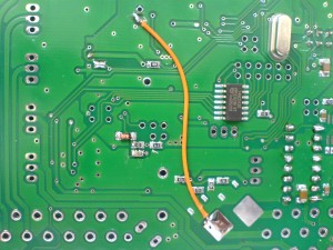
- How can the trigger 2 work when the hall is pulling the ref *pulse down (see image 3) ?
- what is the correct working sequence for Audi trigger? And what *will the signal to the processor look like if using crank home and *hall signal
- Can Vems use the original trigger trimming (inverted home trig. *Of curse) or due I have to adjust the distributor to make it *work?
...............................................................
- on EC36 pin 13 0-4V +- pulse
- measured 0-4 V before R91 => good
- +- 0,1V after R91 => NOT GOOD
- this is indeed a showstopper for sectrig HALL.
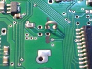
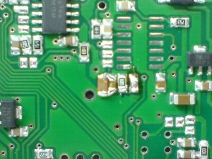
- maybe R91 is cracked ? measure Ohm
- most likely the trace is "shorted" to ground with low resistance. Look for places
- It seems you replaced C33 yourself, check if shorted there.
- Also see D27 (maybe shorted or reversed ?)
- and SJ7 at the bottom, almost under the FETs can be opened to see if the sectrig LM1815 pulls the signal to ground for some reason
- Leaving the sj7 open then i have 0-4 V to the processor. Removed the lm 1815 and still ok signal
- if you purchased bare board, and assembled yourself, this part was not tested with the mintest. So it is even possible there is a short somewhere on the PCB traces
- if you have problems to find the short, while the board is powered, you can use a 0.5 .. +5V strong supply (100mA or higher) to inject current into the short, and measure with DVM mV mode to locate the short. Don't use +12V (or anything higher than 5V), that would kill components. Be careful. If you have max +0.7V supply, or limit with a resistor and diode, you can do the measurements with the board unpowered.
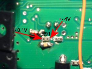
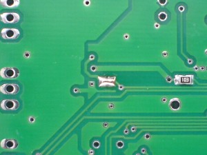
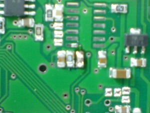
Image2. Measurements with exchange crank home trigger
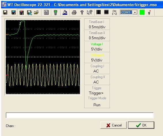
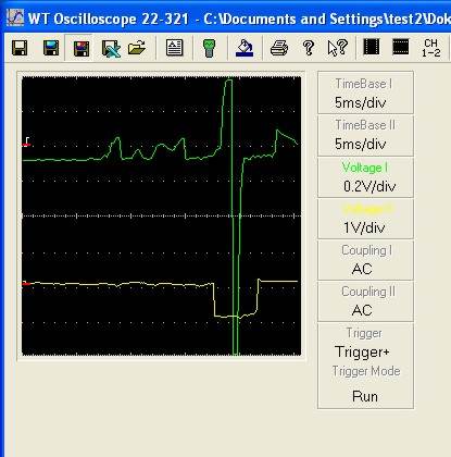
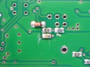
Image 3. Measurements with exchange crank home trigger
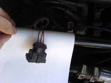
Location of the trigger plug
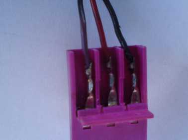
Wiring crank home normal
Swap the red and violet wire
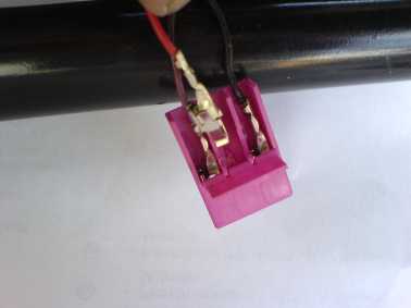
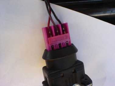
The wire is swapped
Added a 20K resistor (12..15k is better, sometimes 20k is too high)
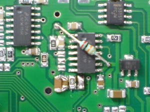
Soldered JP7
Mounting the stepper chip
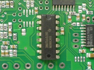
C103 replace with 1nF (only needed on certain boards from a given old batch, 2005 or so)
added 1uF cap in parallel with C40
R182 shorted
Made wire for the crankhome-VR trigger input (EC18 pin 12)
Connected JP 2 and JP 7 so the primary trigger goes where it needs to: