http://www.vems.hu/files/MembersPage/NanassyPeter/CloneInstall/KARKUS_vemspinout.xls
For this im using PhatBobs beautifull Install User guide,
which is currently not covers how to wire up 5 COP's.
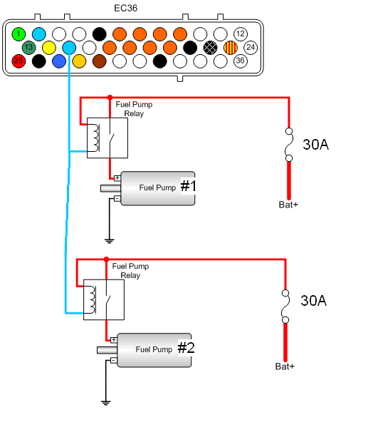
Because of the very high output of this turbocharged engine we will use 2 individual fuel line with 2 fuel pump,and of course 2 fuel pump relays.
Q: Can i run this two relay from the dedicated fuel pump relay output of the vems ECU,namely from the
EC36-pin15?
A: Yes, switching the both relays parallel is no problem at al an should work fine as long as the combined current from the relays does not exceed 250mA (unlikely)
This way
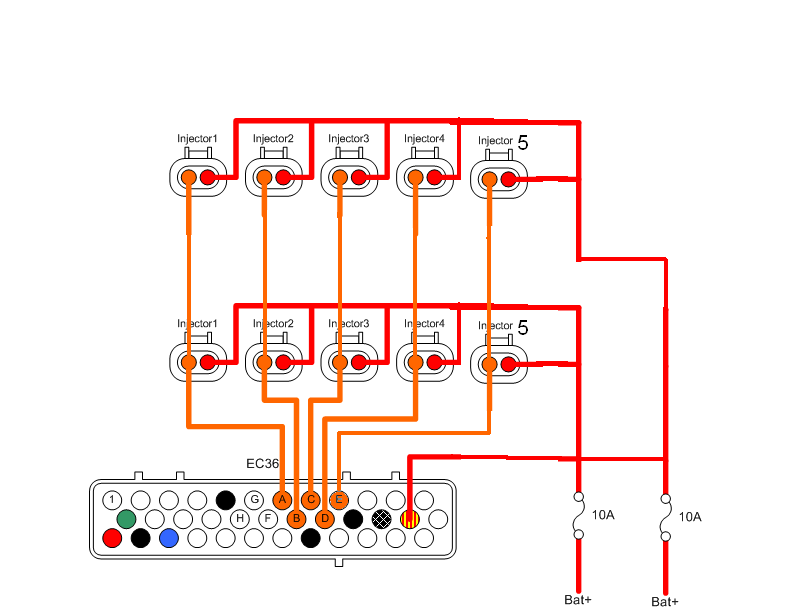
Injector wiring
The schematic below is NOT sufficient to individually switch off one of the injector sets.
Even if you remove a FUSE, the other fuse will supply BOTH sets of injectors (until it breaks, if too low currecnt).
if you insist to the schematic
- I recommend using one 15A or 20A fuse instead of 2 x 10A in parallel. (leave the other fuseholder empty)
- while the engine is off, remove the injector connectors from one set if you want to eliminate the given set.
- it's possible to install relays of multi-circuit switches but they bring more porblem than they solve!
Why don't you connect the 2 sets of injectors to independent injector outputs so you can switch them on/off through software ? That's the only good solution.
- obviously, you don't have enough (5+5=10) injector outputs to control every injector individually
- but max 2 lowZ or max 4 highZ (practically 3 in your case)
- 5 inj output for the primary set, and 2 outputs (2+3) for the secondary set
I found this about AudiTrigger on the relevant page:
How to connect the 3 trigger signals
EC36pin27 - Primary trigger 135 cranktooth VR. Usually no problem
EC36pin13 Sec.trig cam-HALL 1 window camtooth.
don't forget to apply supply voltage for your HALL sensor
EC18pin12 - crankhome VR (1 tooth per crank)
a 1k pulldown to GND and 20..50k pullup (not lower than 10k) towards 5V is necessary.
Original successful trigger setup only used a 10k towards 5V, and no resistor towards GND (other than the sensor itself, of course, which is appr 980 Ohm). A low impedance input helps to keep noise down, and the signal amplitude seemed to be high enough even at very low RPM during Finland-Sweden-cold-winter cranking ).
Important It is necessary to reverse crankhome polarity at the crankhome connection on the firewall (engine bay side), using 3 pieces of wire, 3pin JPT Male and Female connector is needed to make this properly. A good signal looks like [this] at EC18 Pin 12