This tutorial is written to explain all the trigger setup variables for the 1.1.x series of firmware. There are two general types of trigger schemes, those that rely on a missing teeth to identify the wheel position and those that do not. This document deals with the latter.
MembersPage/Fero/SUPRA has a similar (working, tested and proven) setup explained, but with 24 primary trigger pulses per cam revolution, while this has only 4: so at least another_trigger_tooth, tooth_wheel_twidthX and h[1] must be adjusted, and testing is needed.
The examples here are taken from a Mazda 1.8l 4 cylinder BP engine's trigger scheme. With the settings here it should be trivial to make changes and adapt the configuration to variants of this scheme.
First the Mazda distributor contains a disc with slots as follows:
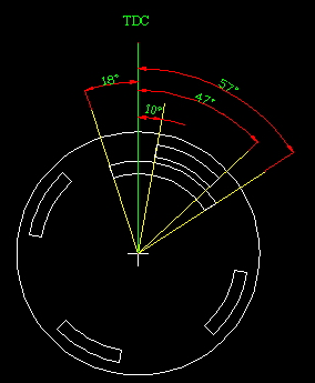
This camwheel rotates counterclockwise and is triggered via hall type sensor. This means either rising or falling edge pulses are appropriate.
Looking closely at this wheel the waveform of a running engine will look like this graphed according to degrees of rotation on the cam. Since the crank rotates at twice the speed this graph also represents two complete crank revolutions.
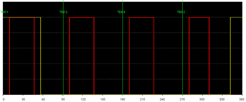
Dissecting the data presented here a number of details can be determined. Note that unless otherwise noted all measurements are expressed in degrees of cam rotation. Here, the primary pulse occurs 4 times per engine period and the secondary trigger only once.
- The rising edge of any primary trigger occurs 80 degrees before TDC on the next cylinder.
- The falling edge of any primary trigger occurs 33 degrees before TDC on the next cylinder.
- The rising edge of the secondary pulse occurs 18 degrees before TDC1
- The falling edge of the secondary pulse occurs 57 degrees after TDC1 and 43 degrees before TDC3.
Since these measurements are in cam degrees they are 1/2 of the crank measurement. This engine will never require 66 crank degrees of advance so we can use the falling edge of the primary trigger. Since this signal will occur closer to the actual engine event it will be slightly more accurate when the RPM is not constant.
First the trigger types must be configured:
primary_trigger
This configuration parameter contains a number of bit flags:
| Bit Position | 1 | 0 |
| 0 | Rising edge trigger | Falling edge trigger |
| 1 | Simple repeating trigger type | Missing tooth trigger type |
| 2 | Filtering enabled | Filtering disabled |
| 3 | Advanced trigger code | Disabled |
| 4 | One missing tooth (ie 60-1) | Two missing teeth (ie 60-2) |
| 5 | Fiat Stilo and Subaru triggers | Disabled |
| 6 | Nissan trigger | Disabled |
Here we wish to trigger on the falling edge, it is a simple repeating trigger type with filtering enabled\n
primary_trigger=06
secondary_trigger
| Bit Position | 1 | 0 |
| 0 | Rising edge trigger | Falling edge trigger |
| 1 | Disable this trigger | Enable this trigger |
| 3 | Single tooth type | Multitooth type |
| 4 | Cam Sync | Alien Advance |
| 5 | reserved for future crank trigger scheme | Disabled |
| 6 | Fiat Stilo and Subaru triggers | Disabled |
The secondary trigger also uses the falling edge and is flagged as the cam sync channel.\n
secondary_trigger=18
tooth_wheel
For 1.1.x series firmwares running in 'non-missing' mode this is the number of primary trigger pulses seen between each camsync pulse. We have four primary trigger slots on the cam.\n
tooth_wheel=04
reset_engphase_after
Reading the source code shows that this parameter is not used therefore its value has no effect on the operation.
trigger_tooth
For 1.1.x series firmwares running in 'non-missing' mode this tells the firmware which tooth to trigg from in relation to the H[1]table. trigger_tooth must be < another_trigger_tooth. For this application this only leaves trigger_tooth=0\n
trigger_tooth=0
another_trigger_tooth
For 1.1.x series firmwares running in 'non-missing' mode this tells the ECU how many steps to take at a time in the H[1]table. For this application we want to use every entry in the H[1]table and which give us another_trigger_tooth=1\n
another_trigger_tooth=1
cam_sync_r_edge_phase
cam_sync_f_edge_phase
These two do not appear to be implemented in the 1.1.x code when used in "non-missing" mode. (not even used to provide a faster sync of the trigger when the cam sync pulse arrives). Both are set to 0xFF
crank_minper
This is the minimum time between trigger pulses. For this application where we use 2 trigger pulses per crank revolution it's 1/(2*8000/60)=0.00375s=3750us The authentic source (global.h) says 16 usec: uint8_t crank_minper;// Cranktigger period minimum (*16 usec)
The docs say this is the minimum period for the crank trigger (actually, between trigger teeth, so 180crankdeg for a 4cyl, even with many crankpulses). It is in 16us intervals.
It's a filter that limit the max trigger frequency.
</code>
tooth_wheel_twidth1
tooth_wheel_twidth2
With no missing teeth these two values are used together as a 16 bit value for the number of degrees between on the primary triggers. This value does not reflect the 74 crank degrees of width in our primary trigger but the 180 crank degrees between falling edges. The value is stored in 1/4 crank degrees. The resulting value is 0x02D0\n
tooth_wheel_twidth1=0xD0
tooth_wheel_twidth2=0x02
ign_tdcdelay -primary trigger pulse to TDC.[1/2 crank degrees]
This parameter is very important as it must be chosen such that there are enough crank degrees of rotation to allow our maximum desired amount of timing advance. Without dwell, of course. (Dwell is started elsewhere so not related to this). Since we use the falling edge of the primary pulse it is 33 cam degrees (==66 crank degrees) before TDC. The resulting hex value in 1/2 degree increments is 0x84 \n
ign_tdcdelay=84
The resulting trigger config for this Mazda BP engine is as follows:\n˙8˙
h[1] reftooth array shows which tooth to trigger from (when firing the relevant h[2] ignition output). Very simple here: 00, 01, 02 and 03 in this order (remember order is right to left, that is bottom to top in megatune).
h[1]=03 02 01 00 .. .. .. ..
Note that this can be rotated, so this (if h[2] rotated the same way) would be fine as well (maybe taking slightly more revolition to start firing during cranking initial syncup):
h[1]=00 03 02 01 .. .. .. ..
---
Debug Info
These settings do not appear to work correctly as the spark timing is way off. I've created an excel spreadsheet to calculate the datalogged results. I am logging the primary, secondary and 2 coil signals. For the coil signals I used a voltage divider so it will float at vbatt/2 volts and be pulled to ground during dwell as my DAQ card will only read -10-+10vdc. Sample rate is set at 10khz to catch the 1.6ms dwell.
| TDCDelay | Prim Down | Prim Up | Trigger | sec/degree | RPM | TDC | Actual Timing | desired timng |
| 0x60 | 2.976 | 3.092 | 3.016 | 0.002188679 | 152.2988506 | 3.070113208 | 24.72413793 | 10 |
| 0x60 | 3.553 | 3.67 | 3.594 | 0.002207547 | 150.997151 | 3.647924528 | 24.42735043 | 10 |