Measuring ignition advance
With a tooth wheel as crankshaft trigger, the genboard can be used to reconstruct the ignition map of an existing distributor or OEM ECU. Since the angular speed and position of the crankshaft are known, it is straight forward to calculate advance. When the config is setup to use a tooth wheel as primary trigger, the advance is measured by letting the secondary trigger tap the ignition coil.
If the firmware is compiled without MS_COMPATIBILITY defined in my_make, the measured advance and dwell can be logged using a program such as MegaTunix. Finally the log needs to be filtered and an ignition map generated, 'bin/linreg.pl' is recommended for doing that automatically.
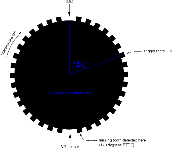
Michael uses a 36-2 teeth trigger wheel with TDC at the missing tooth. The missing tooth is not in the recommend position (max advance + 1..40 degrees) thereby potentially introducing inaccuracies when engine speed varies. trigger_tooth in config is set to the value 10 (dec) which delays the trigger by 10*10 degrees (360 degrees / 36 teeth) and reduces the inaccuracy.
The question is when will the missing tooth be detected? This is important because:
180 degrees = 10*10 degrees - tdc_delay/2 - unknown_detect_missing_tooth_delay
tdc_delay (in this case 70 degrees) can compensate for the unknown delay, but the measured ignition advance table will be offset by a constant. Since the LM1815 gives a rising edge pulse when the VR sensor is in the middle of the tooth, the delay will be 10 degrees after TDC as in the picture.
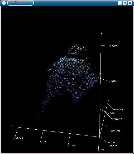
A 20 minutes drive with logging of ignition advance at various rpm/map load points:
x = rpm, y = map [kpa], z = advance [degrees]
(for the interested: ADU9336 ignition control box used in ex. MG Maestro)
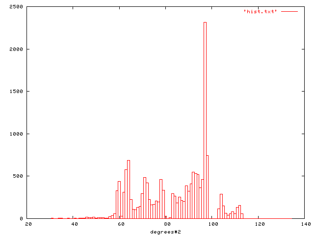
The corresponding histogram showing frequency of advance degrees*2 observations:
logfile: http://caffrey.dk/dump/log_20040318.zip
I extracted statistics from it: simple averaging near gridpoints and running linear regression near the lines between 2 gridpoints: see bin/linreg.pl for both (Marcell).
The holes in the map are indeed strange, a possible explanation is the old ignition ECU having problems generating certain (30/40/50 degrees) advances. It's almost certain that the old slow ECU is processing the high priority tooth-detection interrupt in that holes, therefore it cannot emit spark.
A couple of interesting figures from the log file:
WOT @Â 4000 rpm: 38 degrees
part throttle (50 kpa / 3000 rpm): 55 degrees
idle (30 kpa / 1000 rpm): 30 degrees
Measuring dwell period
Besides measuring when the ignition event happened, the duration of the event is also measured. This can be used to measure the coil charge time - the dwell period. Of course the duration of any other signal can also be measured, ex. injector opening time of existing ecu.
Michael's coil is specified to have a 0.71-0.81 ohm resistance at 20C degrees. Measured dwell is around 4.4 ms.
[A log file] showing how the dwell period changes as a function of battery voltage.
First column is battery voltage (I'm not sure about the voltage divider, max seen battery voltage should be around 13.5V), second column is dwell period in ms.