BMW E30 323 with M20B25 Turbo

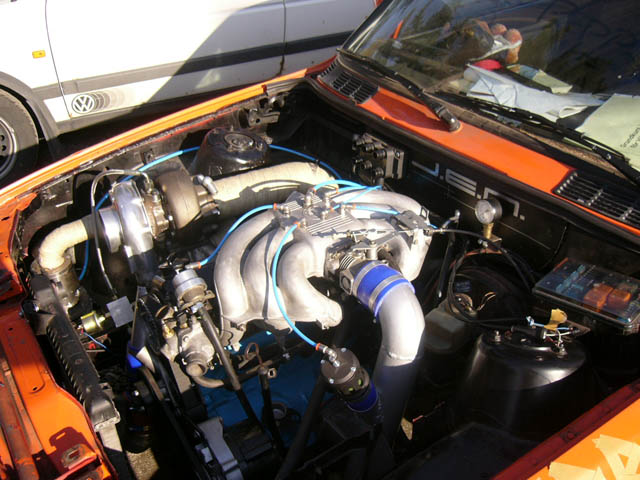
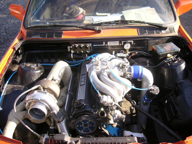

The engine
- Inline 6 cylinder BMW M20B25, 2.5 litres, ignition order 153624.
- Wastefire ignition with Ford EDIS wasted spark coils (stock 60-2 trigger wheel)
- Sequential fuel injection with no cam sensor and low-Z 720 cc/min injectors
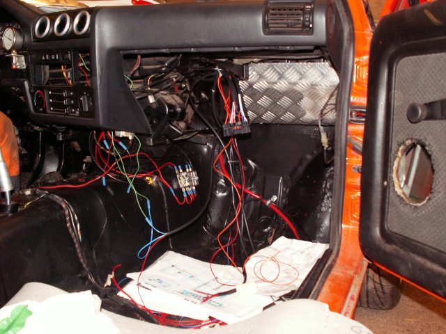
- Custom engine harness
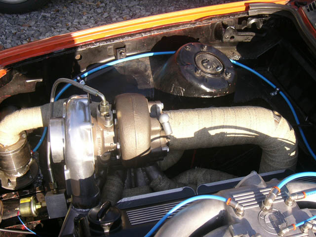
The turbo system
- PPF turbo manifold (pulse-split)
- External wastegate 50 mm from Boström Turbo Teknik
- 3.5" downpipe and exhaust system out through the (no muffler)
- Dump valve by Simon Marmander
- Custom large intercooler
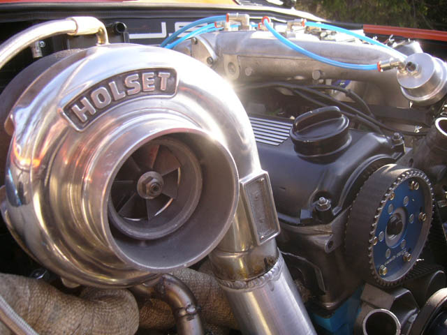
- Holset HX50 turbo
The config and tables will be updated on this page, and documented properly given some free time. Here they are: [config.txt] and [tables.txt]
Bear in mind that fuel has not been set properly, including afterstart and other enrichments.
Changes from 2005
Ignition coils
Above 6000 rpm and some boost this engine ran into a problem with the ignition dwell. The Ford EDIS coils need 4 ms dwell but that was simply not possible since the method used in firmware at the time did not make it possible to use overlapping dwell. At 7000 rpm one revolution of the engine takes 8.57 ms and there are three ignition events. The time between each ignition event is 2.86 ms on a 6 cyl engine, and there is currently 400 us "coil off time" which means an effective 2.46 ms dwell on coils that need 4 ms. The problem would be more serious on a 8 cylinder engine.
The coil dwell limitation had not been resolved by spring 2006 when the car was on the road again. The [high power ignition coils] from Swedish company "Biltema" were chosen and driven in "dual out" mode, which means wasted spark. This has worked well, we have not found their limit yet.
Injector FETs
We have established that poor quality fuse holders caused 2 injector drivers to break. These holders were replaced with more reliable holders with spade connectors that attach directly to the fuse.
I have replaced the damaged FETs, testing on the engine stille to come.
Injector Flyback
The GenBoard/Manual/PowerFlyback has been installed and made a tremendous difference with the injectors. We have found a setting for the injector characteristics that work, more tuning will probably change this but it runs well at idle and the map seems properly flat and uninteresting in this area.\n
injopen = 0
injocfuel = 400 usec
TPIC6A259 aka. P259 chip
Events leading up to this point
When Emil soldered the board he made a poor job with the IGBTs which shorted, besides a risk of really salting the engine, this made it hard to find three working IGBTs required for the initial Ford wasted spark coils. It made it even harder this year when I converted to separate coils to avoid the overlapping dwell problem and needed 6 separate IGBTs. This is when I first opened the case and found out about the IGBT situation. I swapped them all out and soldered them in good.
Now that we got good spark we realised that we had a couple of broken injector FETs but could get 6 FETs that worked and the car was driven aggressively at low turbo boost for 140 kms to break in the engine. This was a completely trouble free time.
Eventually another injector FET died and we only had 5 working cylinders out of 6.
That we had broken injector FETs was also apparent from the initial startup when Emil installed the box. They were most likely damaged from a bad kind of fuse holder (intermittent power to stuff, very apparent problem) but this was taken care of with a good quality fuse holder with spade connectors that go on the fuse directly (rock hard connection actually, hard to free the fuse at times).
This was the second time I opened up the box. I replaced all the FETs but the the box didn't agree once installed in the car, the P259 was dead and ate all the +5V needed for the trigger logic.
Is it enough to just cut off the VCC leg of the P259 or do I have to remove the entire circuit? It isn't really needed anyway, we have free FETs and IGBTs for the fuel pump and cooling fan, with some to spare for boost control later.
The P259 is dead, and I don't know why. After having the Genboard powered up on my desk for a couple of hours with no loads of any kind it had stopped blinking the heartbeat diode. I thought it was just an old worn out diode (don't know what it came from but it blinked dimly all the time and did it's job). A 100 Ohm resistor toward +5V was feeding the diode and that created the only current going through. Could the P259 have been damaged previously somehow and bit the bullet later?
I can't rule out the harness being at fault here, but it has been thoroughly built and tested according to the rules set up in the Wiki and elsewhere. The grounds on this car are good and tested, built like they should be.
Extra pins
No stepper motor chip in place, leaves many EC18 pins free for use.
| EC18-5 | Ground for SCL and SDA |
| EC18-10 | SDA (PD1) - on JP1 connector (current default for AntiLagSystem) |
| EC18-11 | SCL (PD0) - on JP1 connector (current default for shift cut) |
Q: How to enable shiftcut? Through grounding of MCP3208 pin 7?
I can't find a good reference information on this. I will update Wiki accordingly if the answer is given here.