By default the motronic plug and play ecu for the AAN (audi S4/S6) comes with a low impedance resistor 'piggy backed' on top of a higher impedance resistor which is necessary to support the stock Audi PTC (Positive Temperature Coefficient' sensor.
Those customers desiring to switch to using the 1.8t style air temp sensor (which is more accurate) can follow these basic instructions.
1) remove the 4 screws from the ecu case on the opposite side of the motronic connector. There will be 2 or more cables protruding through the backing plate: The serial cable, the harness for the 5 pin wideband and 6 pin 'aux' connector as well as possibly EGT and ps2 cables.
This section is not needed - unless you need to disassemble the device for some other reason (hopefully not). To remove the piggyback resistor it is enough to remove the endplate (already done. One does not need to unclamp the FETs for this simple operation, because the resistor is at the endplate, easily reached.
"Unclamping"
2) with the screws removed, while holding the backing plate push a few inches of slack for each of the cables through the backing plate. The purpose for this is to allow enough slack so that the plate can be turned sideways and pushed THROUGH the case with the cables still protruding through the end plate.
3) remove the 4 screws on top of the ecu that secure the FET clamping plates. remove the clamping plates and set aside.
4) remove the 4 screws from the endplate with the motronic connector.
5) you should now be able to begin pushing the circuit board out of the ecu. push the ecu board in the direction of the motronic connector. you will need to turn the opposite endplate sideways and at an angle to push it through.
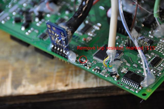
Locate the surface mount resistor that needs to be removed. There are two resistors, one stacked on top of the other. the top resistor is marked '511' or which means 51 * 10e1 = 510 Ohm (or 5100 which is 510 * 10e0 = 510 Ohm, same).
One end of the resistor is connected to the MAT signal. To verify that you found the correct resistor, verify with DVM: you can measure almost 0 Ohm between MAT signal and one leg of this "internal pullup" resistor. This gently pulls up the MAT signal to +5V, allowing the sensor to pull down voltage somewhat (towards ground, in function of temperature).
Remove ONLY the top resistor. The resistor is located near the MAP sensor at the back of the circuit board.
Once the resistor is removed you are ready to re-assemble the ECU. When re-fitting the clamping plates, be sure to mount them so that the 'curve' of the plate bends away from the circuit board. also be sure that the clamping plates do not touch the pins of the FETS!
Once everything is back together the firmware will need to be re-uploaded with the 1.8t air temp sensor ("NTC 2252/256") calibration curve which is beyond the scope of this document. Contact the VEMS dealer you purchased your ECU from for assistance.