Navigation
- Main MembersPage/KoabiBrooks
- Idle MembersPage/KoabiBrooks/Idle
- Ignition MembersPage/KoabiBrooks/Ignition
- Injection MembersPage/KoabiBrooks/Injection
- Trigger MembersPage/KoabiBrooks/Trigger
- Wiring MembersPage/KoabiBrooks/Wiring
- Q&A MembersPage/KoabiBrooks/Questions
IGNITION PAGE
I need to figure out what the 4 pins are for on the connector. Disclaimer, the info below is all based on assumption...
- 4 pins - THIS IS HOW WE THINK IT WORKS
- pin 2 for 1 pair of cylinders and pin 3 for the other pair of cylinders. Dwell while active (+5V) and fires when falling back to GND. This is common for active coils
- 1 pin for power supply
- 1 pin for ground
- New Theory:
- Coilpack is triggered on +5v instead of switched ground
- to be determined...
- also possible
- 1 pin for power supply
- 1 pin for ground
- 1 pin to trigger spark
- 1 pin as HV (secondary side) return (easy to test: appr 10..20kOhm with the sparkplug connection, maybe only in one direction)
Diagnosing the VR6 coilpack:
Pin 1 - power, Pin 5, ground
1) Disconnect the 5 pin harness connector from the ignition coil power output stage
2) Connect a voltmeter across terminals 1(-) and 5(+) in the connector. Turn the ignition on and check that battery voltage is present.
3) Remove fuse no. 18 (fuel pump, H02S control module) from the fuse/relay panel.
4) Connect an LED test light across terminal 5 and terminal 2 in the harness connector. Actuate the starter and check that the LED flashes.
- If the LED does not flash, the ignition (ground) signal for cylinders 1 and 6 is not present. Check the wiring between the coil and the ECM connector. If no faults can be found, the ECM might be faulty.
- If the LED does flash, but the spark plugs for cylinder no 1 and cylinder no 6 do not fire, the ignition coil/power output stage is faulty and should be replaced.
5) Repeat above step across terminals 5 and 3 (cylinders 3/4) and terminals 5 and 4 (cylinders 2/5). If any faults are found replace ignition coil/power output stage.
Diagnosing a mkIV 2.0 (AEG):
Ignition Coil and power output stage, testing (2.0L)
Two double - ended ignition coils are mounted in a common housing together with an power output stage. The power output stage takes the low power signal from the ECM and boosts it to a level useable by the ignition coils. The signal to fire a spark plug results in both spark plugs on that particular coil firing at the same time. One spark is “wasted” by the unused cylinder because it occurs at a time when it is not needed. The other simultaneous spark is used to fire the mixture in the normal manner. The unused spark causes no additional wear on the spark plug because it occurs at a time when there is minimal heat and pressure on the plug. The power output stage cannot be directly tested, but the signal from the ECM along with power and ground can be easily tested. The ignition coil can also be checked.
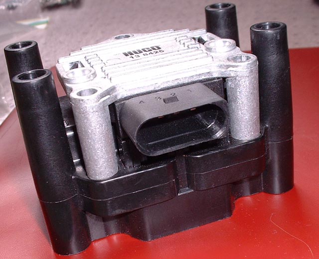
- Remove harness connector from the ignition coil power output stage as shown earlier . (Picture shows AEG four pin connector, counting one at the square end to four at the round end)
<On AEG engine: Connect a voltmeter to disconnected connector at terminals 2 and 4.
- Switch on ignition and read voltage. If voltage is present, proceed to next step. If no voltage is present, check for breaks or open circuits in the wiring. See 976 Wiring diagrams, fuses and relays.
SPECIFICATION: Voltage supply power output stage.....11.5Volts minimum
- Switch off ignition.
- Remove fuse 32 (for fuel injectors) as shown earlier.
- Connect an LED test light only (such as VAG 1527B) to the disconnected connector at terminals 2 and 4 (AEG)
- Operate starter and check for a signal from the ECM. LED test light must flicker.
- Repeat steps 6 and 7 with the LED test light in terminals 3 and 4
* If LED test light flickers , signal form ECM is good and ignition coil with power output stage should be replaced.
- If test light does not flicker, check for break in wiring. See 97, wiring diagrams, fuses and relays. If no faults are found, check ECM for DTCs with a suitable scan tool.
- use a high quality digital automotive multimeter and LED test light to make the tests. An analog (sweep needle) meter and conventional test light should not be used as they can permanently damage electronic components.
- Always connect and disconnect the ECM connector and meter probes with the ignition off to avoid damage to electronic components