Alfa Milano(75) gold
First pass will be a PNP in to the L-junk plug.
I need to do this fast.
Will be using hall dizzy trigger.
Will feed a Street Fire CDI unit for spark
Using a old V3.2 with no step chip.
notes:
l-jet pin1 yellow to feed white of cdi
gray of cdi to tach white
red of cdi to coil power (green/black)
NOTE: Lo-Z Injectors
Ignition pull
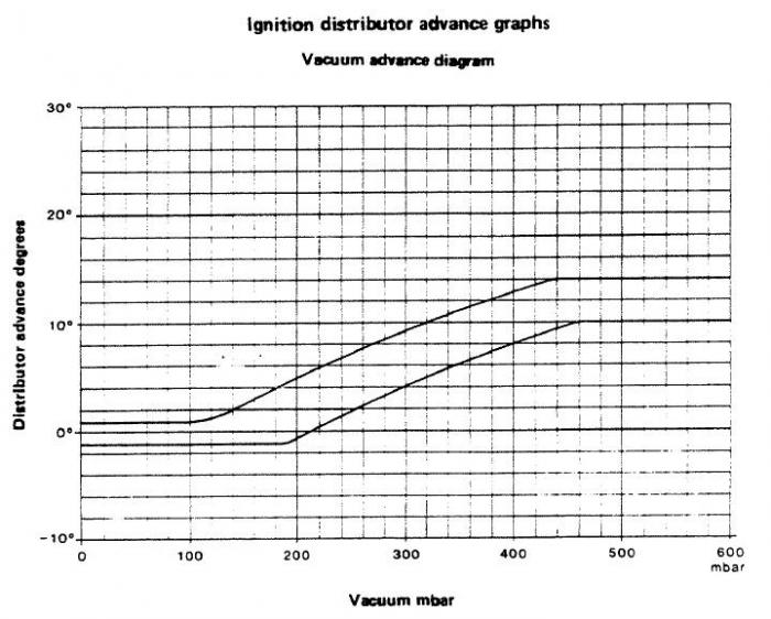
Just the spark box extra advance is added at the dizzy with the ported vac advance
Note vac advance is not manifold vac but a port near the butterfly
| WOT switch set | ||||||||
| 7.25 | 10.25 | 17 | 22.5 | 26 | 29 | 31.5 | 33 | 33 |
| With switch open (not WOT or idle) | ||||||||
| 700 | 1300 | 1800 | 2400 | 3000 | 3600 | 4200 | 4800 | 5400 |
| 7.25 | 10.75 | 17 | 23.5 | 28.5 | 32 | 34.25 | 36 | 36 |
| Idle switch set | ||||||||
| 2 | 3.75 | 14 | 23.5 | 28.5 | 32 | 34.25 | 36 | 36 |
Spark Box pinout
AMP 480004-5
| /****************spark box connector******************\ | ||
| blk-gnd | gnd | powwer from coil |
| yel-coil-driver | yel-hall_power | blk-sig |
Ignition
Going use the stock driver at first logic level output 2
Later going to use normal driver output 0
| L-jet Pin | Wire Color | number in setup | ECIII pin |
| NA spark box | Yellow | Ignition output 2 | pin34 |
Injection
Using old wires.
I need to look at the car but the diagram out of the online books page E-43
each injectors has a red wire for power via S2 relay looks UNFUSED!!!
To ECU
| L-jet Pin | Wire Color | Injector # | number in setup | ECIII pin |
| pin#31 | Light-blue/yellow | 6 | INJF | pin18 |
| pin#30 | White/red | 5 | INJE | pin9 |
| pin#14 | Light-blue/red | 4 | INJD | pin20 |
| pin#32 | Yellow/black | 3 | INJC | pin8 |
| pin#33 | Orange/white | 2 | INJB | pin19 |
| pin#15 | Green/white | 1 | INJA | pin7 |
TPS
| TPS switch (need to get a motronic pot type) | ||||
| L-jet Pin | Wire Color | Use | number in setup | ECIII pin |
| pin#18 | Purple | common | TPS | pin1 |
| pin#3 | Yellow | WOT | TPS5V | pin28 |
| pin#2 | White | idle | GND | pin26 |
IAC
Heater might just keep it on most of the time?
one pin goes to the S2 power fuel pump/O² Orange/black
| L-jet Pin | Wire Color | Use | number in setup | ECIII pin |
| pin#34 | Orange | will be the IAC control | INJG | pin6 |
| N/A | S2 power | N/A | N/A |
S2 Relay enable
it looks like l-jet pin#28 Yellow/red need to go to ground to enable the S2 double relay
Fuel Pump/O² Power Control
l-jet pin#4 Grey/green looks to high while cranking and will power part of S2 fuel pump/O²
| Fuel Pump/O² Power Control | ||||
| L-jet Pin | Wire Color | Use | number in setup | ECIII pin |
| pin#28 | Yellow/Red | S2 Relay enable power fuel pump/O²/injectors/etc | INJH | 17 |
Fan
| Fan Reley | ||
| Wire Color | Use | ECIII18 pin |
| N/A | N/A | |
Tachometer
| Tachometer | ||||
| L-jet Pin | Wire Color | Use | number in setup | ECIII18 pin |
| N/A | N/A | coil also goes to cluster(tach?) | N/A | N/A |
WBO²
ground the green coex to gnd
| WBO² | ||||
| L-jet Pin | Wire Color | Use | ECIII18 pin | WBO² pin |
| part 9 | Light-blue/white | PUMP(-) | 7 | 5 |
| 12 | Light-blue/black | PUMP(+) | 9 | 6 |
| 24 | Green coex | NERNST_CELL1 | 13 | 1 |
| part 6 | Green | HEATER1(-) | 18 | 4 |
| N/A | Orange/black | Power | N/A | 3 |
| Power will come from the old wire that went to the NBO² | ||||
Crank Trigger
| Crank Trigger Use one of the big green coex | ||||
| Wire Color | Use | number in setup | ECIII pin | Spark Box |
| Black | TRIGG1_CONN | 27 | Hall Sig | |
| Black Shield | GND | 26 | Hall Gnd | |
CAM Triger
N/A
CLT
| L-jet Pin | Wire Color | Use | number in setup | ECIII pin |
| 13 | Brown | CLT | CLT | 14 |
| N/A | Black | Gnd | Gnd | 26 |
IAT
need to be looked up AFM temp
| L-jet Pin | Wire Color | Use | number in setup | ECIII pin |
| 8 | MAT | 2 | ||
| 9 | Gnd | Gnd | 26 |
Serial Port
| Wire Color | Use | number in setup | ECIII18 pin | DB9 |
| Blue | RxD | RxD | 14 | 3 |
| Purple | TxD | TxD | 15 | 2 |
| Green | Gnd | Gnd | n/a | 5 |
Power
| Power | |||||
| L-jet Pin | Wire Color | Use | number in setup | ECIII pin | Sparkbox |
| pin#29 | Red | power shaired with injectors from S2 | FLY | 23 | |
| part 15 | Grn/black | power from coil Key switch | +13.8VBATT | 25 | Green/Black |
| pin#20 | Pink/black | looks to power S2 fuel pump/O² | tie to +13.8V | Green/Black | |
| yellow | dizzy hall power | tie to +13.8V | yel-hall_power | ||
| Grounds | |||||
| L-jet Pin | Wire Color | Use | number in setup | ECIII pin | Sparkbox |
| pin#5 | Black | ground to CLT | GND | 26 | |
| pin#16 | Black | power grounds | GND5 | 32 | Black coil driver |
| pin#17 | Black | power grounds | GND5 | 21 | Black shield Hall driver |
| pin#35 | Black | power grounds | GND5 | 5 | |