I reused the old wires I think that might slowed thing down a lot. but I got to keep the nice sealing of the OEM wires.
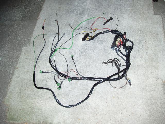
after working in the Black car in 108°F temps I notice the whole harness can come out easy. so I pulled it out and did a lot of the work in the shade
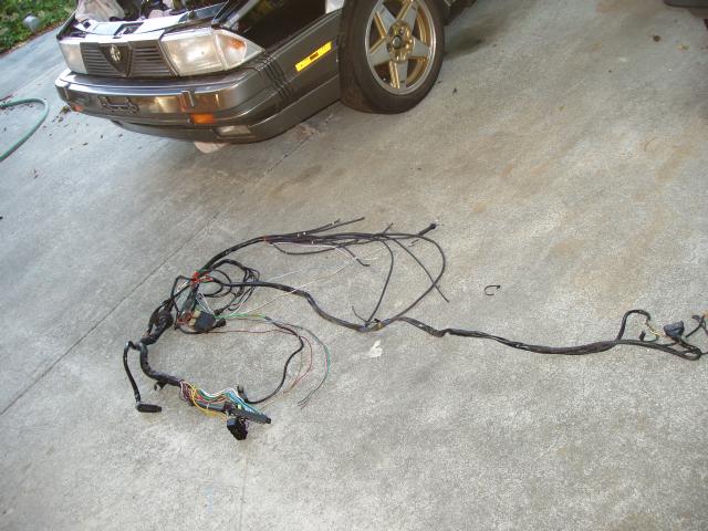
Then after the work
COP wiring
I used 2 sets of the VW harness part# 1J0-971-658-L
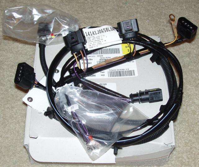
the COPs
part# 06B-905-115-N
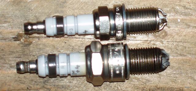
you need the short sparkplugs like a camerry I think the 24V use the right plug too.
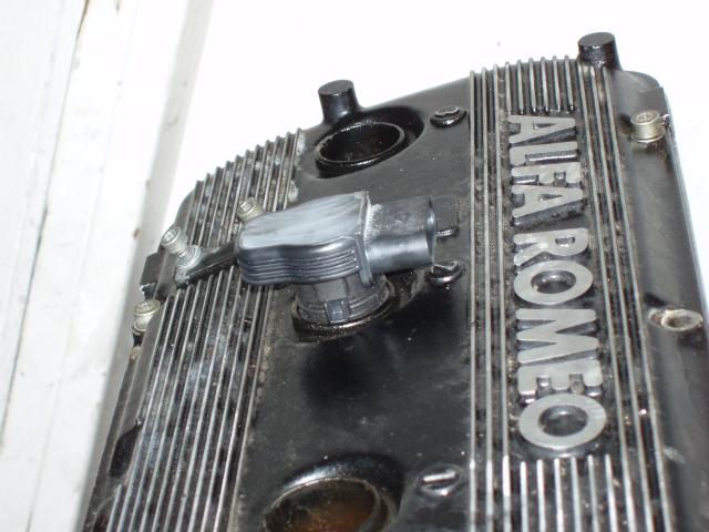
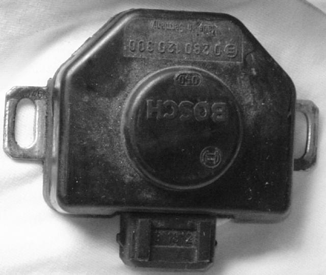
Non-Working TPS
This is the old switch type every one that looked like this in the junkyard was a switch this is no good.
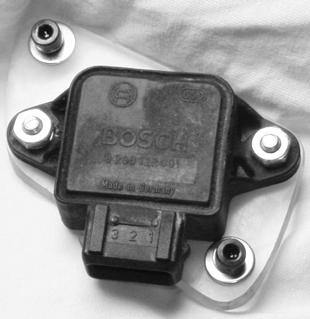
Working TPS
This type is has a pot inside look for this type at the junkyard.
the mounts are different but a ¼ inch chunk of plastic and a drill will fix that.
COP Drive
it is 5V so I need re-think this
I changed the coil mosfet resistors to 1K
at Q3 Q6 Q9 Q12 Q16 Q21
jumped gate drive to output.
added diodes out to ground this will clamp any negitive voltage on the outputs
5.1V zeners would be a beter but I did not have any.
I ended up with a NPN driving a PNP giving me a strong 0 to 12V
but I do not think it was needed.
COP setup
| The pairs I will use so I can run wasted is | |||||
| L-jet Pin | Wire Color | Transistor | number in setup | ECIII pin | cyl |
| 2,3 | White,Yellow | Q16,Q21 | #0,#1 | pin35,pin33 | 1,5 |
| 18,11 | Purple,White/black | Q6,Q9 | #4,#5 | pin11,pin12 | 4,3 |
| Spark7,part 6 | Purple/white,Green | Q12,Q3 | #6,#7 | pin10,pin24 | 2,6 |
Injection
Using old wires.
I need to look at the car but the diagram out of the online books page E-43
each injectors has a red wire for power via S2 relay looks UNFUSED!!!
To ECU
| L-jet Pin | Wire Color | Injector # | number in setup | ECIII pin |
| pin#31 | Light-blue/yellow | 6 | INJF | pin18 |
| pin#30 | White/red | 5 | INJE | pin9 |
| pin#14 | Light-blue/red | 4 | INJD | pin20 |
| pin#32 | Yellow/black | 3 | INJC | pin8 |
| pin#33 | Orange/white | 2 | INJB | pin19 |
| pin#15 | Green/white | 1 | INJA | pin7 |
TPS
| TPS switch (need to get a motronic pot type) | ||||
| L-jet Pin | Wire Color | Use | number in setup | ECIII pin |
| pin#18 | Purple | common | TPS | pin1 |
| pin#3 | Yellow | WOT | TPS5V | pin28 |
| pin#2 | White | idle | GND | pin26 |
IAC
will use the same pins the powered the heater in the old thermo type
one pin goes to the S2 power fuel pump/O² Orange/black
need to add a flyback diode between the pins.
| L-jet Pin | Wire Color | Use | number in setup | ECIII pin |
| pin#34 | Orange | will be the IAC control | INJG | pin6 |
| N/A | S2 power | N/A | N/A |
S2 Relay enable
it looks like l-jet pin#28 Yellow/red need to go to ground to enable the S2 double relay
Fuel Pump/O² Power Control
l-jet pin#4 Grey/green looks to high while cranking and will power part of S2 fuel pump/O²
| Fuel Pump/O² Power Control | ||||
| L-jet Pin | Wire Color | Use | number in setup | ECIII pin |
| pin#20 | Pink/black | looks to power S2 fuel pump/O² | STEP_A | small#4 |
Fan
| Fan Reley | ||
| Wire Color | Use | ECIII18 pin |
| STEP_C | 5 | |
Tachometer
| Tachometer | ||||
| L-jet Pin | Wire Color | Use | number in setup | ECIII18 pin |
| Spark3 | Green/black | coil also goes to cluster(tach?) | STEP_B | 10 |
WBO²
ground the green coex to gnd
| WBO² | ||||
| L-jet Pin | Wire Color | Use | ECIII18 pin | WBO² pin |
| part 9 | Light-blue/white | PUMP(-) | 7 | 5 |
| 12 | Light-blue/black | PUMP(+) | 9 | 6 |
| 24 | Green coex | NERNST_CELL1 | 13 | 1 |
| part 6 | Green | HEATER1(-) | 18 | 4 |
| N/A | Orange/black | Power | N/A | 3 |
| Power will come from the old wire that went to the NBO² | ||||
Knock
| Knock Use one of the big green coex | |||
| Wire Color | Use | number in setup | ECIII pin |
| Yellow | KNOCK1 | 34 | |
| Shield | Knock gnd | 36 | |
| Black | KNOCK2 | 23 | |
Crank Trigger
| Crank Trigger Use one of the big green coex | |||
| Tie the coex shield only to the VR shield | |||
| Wire Color | Use | number in setup | ECIII pin |
| Yellow | TRIGG1_CONN | 27 | |
| Black | GND | 26 | |
CAM Triger
| CAM Triger use the black coex | |||
| Wire Color | Use | number in setup | ECIII pin |
| 1 | Yellow | TRIGG2_CONN | 13 |
| 8 | Brown/White | GND | 26 |
| 27 | Grey/red | 5V | 27 |
| N/A | Red/black | 12V | N/A |
CLT
| L-jet Pin | Wire Color | Use | number in setup | ECIII pin |
| 13 | Brown | CLT | CLT | 14 |
| N/A | Black | Gnd | Gnd | 26 |
IAT
| L-jet Pin | Wire Color | Use | number in setup | ECIII pin |
| N/A | MAT | 2 | ||
| Gnd | Gnd | 26 |
Serial Port
| Wire Color | Use | number in setup | ECIII18 pin |
| Red | RxD | RxD | 14 |
| Brown | TxD | TxD | 15 |
Power
| Power | ||||
| L-jet Pin | Wire Color | Use | number in setup | ECIII pin |
| pin#29 | Red | power shaired with injectors from S2 | N/A | N/A |
| pin#10 | Red/black | power direct from S2 | +13.8VBATT | 25 |
| Grounds | ||||
| L-jet Pin | Wire Color | Use | number in setup | ECIII pin |
| pin#5 | Black | ground to CLT | GND | 26 |
| pin#16 | Black | power grounds | GND5 | 32 |
| pin#17 | Black | power grounds | GND5 | 21 |
| pin#35 | Black | power grounds | GND5 | 5 |