I'm about to try getting VEMS running on my Saab 9000 2.0 Turbo -89. And hopefully i'll learn more about electronics during the installation process (newbee at the moment). And helping two of my friends to install VEMS on their cars.
Thanks for the replies and help i've gotten so far
050527
- Can i use ordinary cable from AD597 to EC18 and connect EGT cable there? If not i will mount a connector on the case and use a thermocouple cable to AD597.
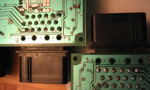
- Late answer I know.. I've tried it on one particular setup, and it made 20-30 C difference at 600-700 C and the error was constant. To be anal about it, do it properly with real K-compensational cable and K-connectors in the front end plate. [Like I did here] It didn't take much effort really. /Mattias
![[Like I did here]](http://www.vems.hu/files/MembersPage/MattiasSandgren/VolvoPV/pv_vems_box_not_clamped.jpg)
050526
- Q: When i turn on my genboard all inj drivers light up (A,B,C,D,G,H)
- This is the priming pulse. If you have primep=00 setup your board for PWM capability: see GenBoard/VerThree/LowZInjectors especially the R network and R154
- I have primep=00 in config, but missed R154 will try that tomorrow.
- Q: Soldered 1002 resistor on R154, all inj channels still light up on boot. What more can i check?
- When I table test v3.1 I noticed the same, R154 10k was not enough. Even another 10k in parallel didn't help, but 2.48k did the trick and no more unwanted pulse on boot at all. Maybe my boards fuse bits aren't set because pulse with 10k/5k was as long as 316mS! (measured with scope at fets gate)
When the AVR boots:
- AVR's supply voltage raises above BOD (brown-out-detection) threshold, appr. 4.0V
- appr. 65 msec delay (assuming "slowly rising power") from AVR's internal RC. This can be made shorter, to appr. 4 msec by programming a fuse bit with GenBoard/Firmware/Upload
- setting injectors to output and off is apparently the first instruction the firmware does (ioinit() called from vems.c)
- if the pulse is shorter than 500usec, it does not worth to bother. Above 5msec it worths serious investigation.
- Q: I measured 0.22 volt from FET to Flyback with DVM in diode test mode, is this ok?
- if 2 diodes are connected in series (low voltage flyback): normally we measure 600..1200mV or so. 220mV is a bit on the low side, but it can be OK. Measure in the reverse direction as well, it should be "inf".
- I use "M 724 B14 ZP" for the flyback (from rescue kit), also got 2 "ES2J" diode measured them, gave me 782mV. The DVM sends through so little current when measuring, that it's not representative. With 1..2A current it will be >1V instead of 220mV, and difference between ES2J is insignificant. I wouldn't change them.
050526
Some pictures of the progress.
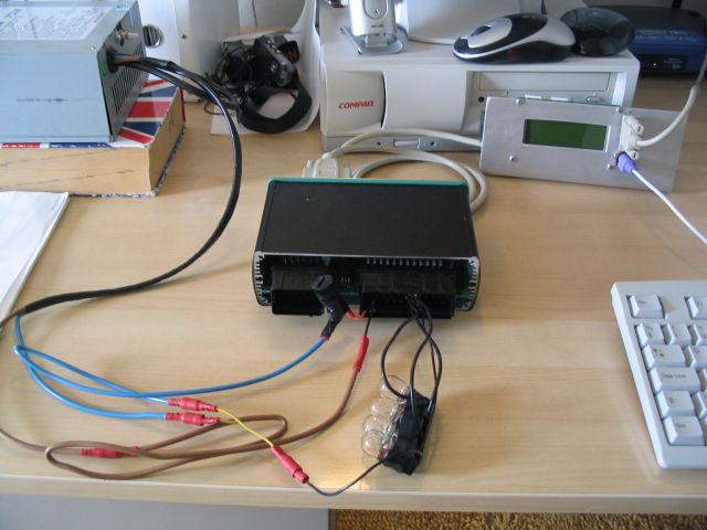
My work setup
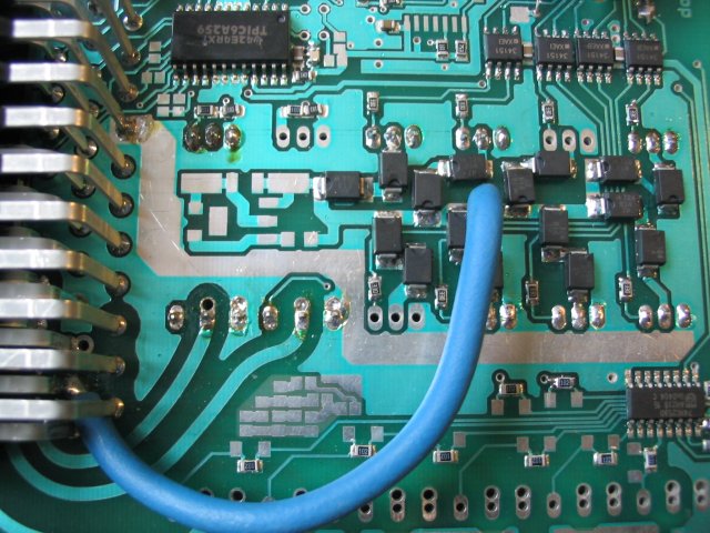
Flyback
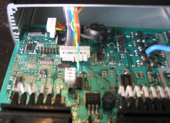
My internal connectors

Inj+Ign+Boost+Idle
050509
- I have now soldered all the injector, ignition, idle, and boost drivers also completed flyback.
- How does mdh command work? eg.mdhf2 turns on I259_7, from where comes f2? If i want to turn on I259_2 what mdh command woluld i use? I have been reading everything that i can find about mdh on the site.
- Check GenBoard/Manual/DigitalOut/Table , i just added some more details..
050509
- Is the "M o16 LV diode" the transient suppression diode used for "high Z","high voltage" flyback? Is it the same as the "332 6V8 diode"? Are you sure it is "M o16 LV diode" ? If in doubt, apply 24V through 1k resistor (try both directions) and see if some current flows in both direction (current will flow in one direction for sure: the diode drops appr. 0.6V in one direction and the other is the question).
- "The low voltage type is definitely suggested if capability of driving highz or lowz injectors is required without HW change." (from the manual). But it's ok to use low voltage flyback with high Z injectors too, there are no reliability problems. (low voltage flyback is actually running cooler!). The reason for several types of flybacks was that with inferior basic injector-opening model the low-voltage flyback was hard to tune at idle. Since the advanced injector-opening model was developed: GenBoard/Manual/Config/InjectorOpening even 1600cc/min injectors on 550cc cylinders can be tuned even with low-voltage flyback.
050507
Back on track again, after a quite long brake. Changed apartment.. lost interest.
Tuned in WBo2 and now going to finish the rest.
- How is it possible to tune freeair to 20.95? On the LCD i see 20.8-21.0, mostly 20.9.
- that's perfect
Use "M 724 B14 ZP" diodes should for "DD Flyback low voltage", they are similar to ES2J.
Injection (flyback), Ignition, EGT, inputtrigger and maybe knock.
040708
Maybe a stupid question but witch are the "SMD 5.1v zener"? (for EDIS) The zeners look like the normal LL4189 diode, but they clamp at -5.1V. It is very easy and safe to apply 8..20V through a 500..5000 Ohm resistor, and see the zener clamp at 5.1V Uca (between cathode and anode). Both the zener and the diode clamps at appr. 0.7V Uac.
And how is the SAW connection made? A common way is using a FET in the place of an IGBT, and a 1k pullup to 5V. (and approporitate configuration so EDIS output control is used, not dwell-based dummyign; see ign_out).
BTW: should we change the semantics of h[2] elements so it uses digitalout() so any output can be used for ignition ? It would only cost a few clock cycles.
040706
Recived a new MAX232-chip from Marcell (thanks), soldered it and now its working.
Feels good to have the genboard up and running so i can countinue the building.
040628
Tested the MAX232-chip yesterday.
- Measured between "JP_ISPI Pin 4" and "GND" with 5.23 volts added to "SV2 Pin 1"
- This gave me 4.99 volts on the broken genboard and 0.003 volt on the working genboard.
So if i assume right the MAX232-chip is broken.
Was the RX-port on the genboard tested before shipping?
Yes, of course, it's part of the test procedure. In fact only the bootloader is sent via ISP, the test firmware is uploaded via RS232 (uploading the firmware with BootLoader, or even just verifying it requires both dir of the bidirectional communication working).
I've seen small solderer particles cause short (that's why it is a good idea to clean the board), but never seen a broken MAX232 chip. The MAX232 is actually more durable than most other chips. Did you have the RXTX connected to (the free pins of) EC18 already? Wasn't something special accidentally connected to the given pins?
I havent connected it to EC18, maybe it got broken when i turned the rs232 connector the wrong way around, as i wrote earlier that i did. Anyhow it working now. Ok. that explains. We thought the max232 is quite tolerant to connect output to output, but it is still illegal. Unfortunately we cannot add a resistor to the output, as it would reduce cable range severely, which is already small: The non-symmetrical drive sucks (RS232, 1-wire) vs. symmetrical (Ethernet, RS485, CAN).
040624
Im still trying to find whats wrong with my RS232-interface, done some meashuring (ohms) on the JP_ISPI.
- Pin 2-7 45,5 Kohm on the broken board
- Pin 2-7 395 Kohm on the working board
Could the MAX232-chip be broken, any way to check it?
Tried to start the Bootloader by shorting RXD and TXD on the JP_ISPI, it worked. But not on the SV2... I really need more hints, cant find anything visually anyway.
It is very easy to check the MAX232. You already checked that AVR =>PC direction is perfect.
- First you apply +5V to the signal that goes PC => MAX232 and check if MAX232 => AVR signal is appr. 0V
- than you apply -5V to the signal that goes PC => MAX232 and check if MAX232 => AVR signal is appr. 5V
This is correct behavior, as the MAX232 is inverting. You can measure the signal near the max, and near the AVR, they are supposed to be the same.
If you have a scope, it's easier, of course (make the PC send characters, eg MegaTune will send 'aaaaaa'...
040622
The recive port on the genboard seems to be broken. I can type mcd on the genboard (PS2) and i get config in Brayterm. But bootloader wont start. In that case you can check the given (1) trace visually and with DVM (for continuity and short).
Tried my other genboard im working on, it worked fine.
Should i try upload the firmware to the genboard through isp with parallel cable. (That is unlikely to fix if there is a trace problem).
Have you tried shorting rx with tx at powerup to enter bootloader? You cannot enter bootloader with a InputTrigger active (except with prog.pl using the 'f' flag), Maybe problems with the trigger circuit? //Emil
Tried that, works on the other genboard i have. And the boards has exacly the same setup so far.
Q. When the bootloader is active how should the lcd look?
A.the bootloader does not ever send command to the LCD, and the LCD keeps content whatever was on there before. (2 lines of black squares out of 4 if the LCD hasn't even been initialized since powerup. If neither good text, nor scrambled text, nor 2 lines of squares appear on the LCD, than you know the LCD does not get power, or contrast setting is bad or LCD is broken).
Squares in the midde lines? This is what i got on the other genboard and it answers "AVREFI1" when i type "S"
Squares in the midde lines is normal when you go directly to BootLoader after powerup (so those LCDs get power and contrast setting is OK).
040620
Managed to communicate with GTKterm, seems to work fine.
But megatunix wont connect. Make sure you exit the 'Man' mode by typing 'bye'. Make sure nothing uses the serial port (try fuse /dev/ttyS0 linux command).
If i turn the cable connected to the genboard the wrong way (?????) around it connects but i get crazy readings. (does NOT sound good. you should use the same connection that worx in Man mode)
This is my cable
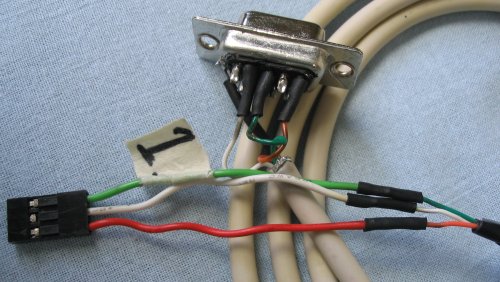
Got the keyboard working!!! It was the cable...
Johan, I think this is normal for LCD to look this way with no sensors or input trigger connected. Values dont change unless keyboard commands are used. If keyboard cable is good, let us know what commands you are using exactly.~Chris
040608:
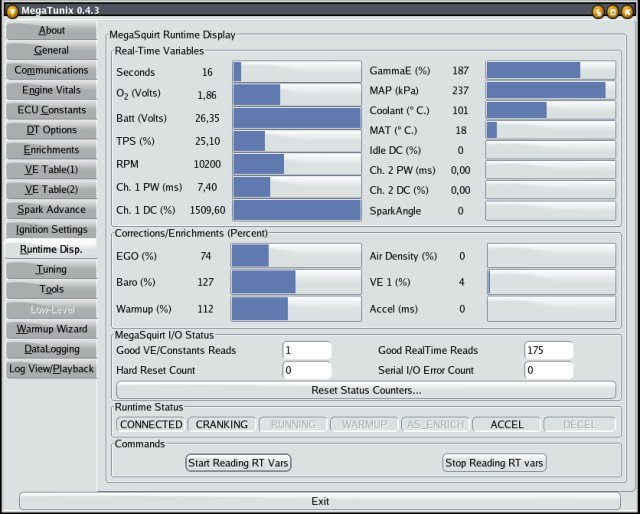
Am i in big trouble? I've connected the genboard for som testing, see if it works. I havent sorted out the earlier issues yet, but i dont think it has anything to do with my problems that i've got now.
Batt (volt):26,35?????. My power supply is from a computer, it measures 11.52 volts. Johan: Is it ok to use computer powersupply? MembersPage/JohanEriksson: I use the PC supply when testing my V3.0
The voltage divider changed from 20k,100k to 22k,75k. True, we need to make this configurable to match the R13/R6 ratio - very good beginner level firmware excercise Johan: Don't relly get this... (sorry, it's spelled exercise)
R6 was missing from my v3.1 board, and it's also missing from yours (based on the photos). It should be 22K (marked 22E), and can be found in the rescue kit. Fitting this will pull the voltage down to something closer, and then can be fine-tuned in the config. - Rich.
Someone already did this firmware exercise (Dave?) -> actually Marcell did it, try adding batt_cal=BB to your config (GenBoard/InitialConfig) Emil (use batt_cal=BB as a starting value only, calibrate with DVM (measure on the 75k VBATT side, and adjust batt_call in config until the megatune voltage matches the DVM voltage) Dave
I measure current consumption to 90mA. -That's OK, depends on HW config- I have only grounds connectors and 12volt connected. There is always some value on sensor signals, just all around the place if you don't connct it (connect GND to unused signals).
I've tried megatune aswell with the same result.
Measured between "HALL_SUPPLY" and "GND", no short but:5.49Kohm wich is the same value as between "+13.8VBATT" and "GND". Got the same values on both of the genboards.
what voltage do you get on HALL_SUPPLY? with it powered Johan: 4.97volt
Big trouble??
040531: I have recived a couple of Vems 3.1 boards. (I'm going to help two friends of mine to install Vems in their cars aswell.)
Some of the components from the rescuekit:
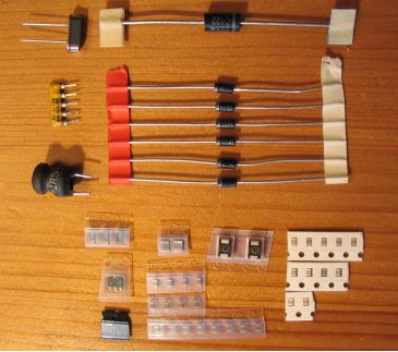
Is there any polarity of capacitors? NO Not the ones in rescue kit
I've made a little PDF-guide of the resistors i've recived that makes it a little easier to find the right value. [resistor guide]
I've done some soldering: Connectors in place 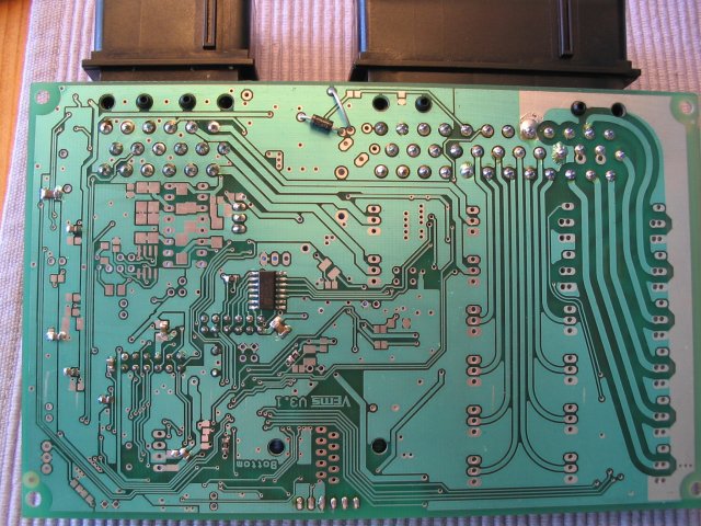
I've got some problems. After soldering one of the boards i realized that the frontplate won't fit, because the board is too wide... (I guess we should add it to the installation section so not only EC soldering height is checked to match frontplate exactly but boardedge to ECpins too: actually EC must be soldered while frontplate is on. How much is the difference? Maybe you can use a small file to remove 0.2mm off the PCB or from the endplate - around the 3 sections where the conflict is - I wouldn't desolder. )
What to do? I'm not to keen on desoldering the connectors.. Desoldering is all about the tools, It takes about 10 min to desolder with a good vacuum desolder iron
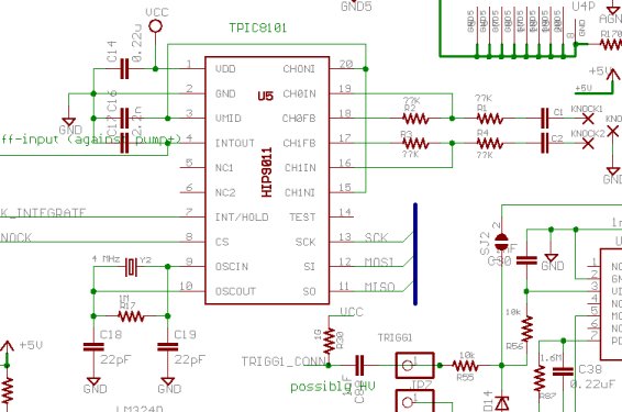
I've soldered the AD597 chip for EGT: Just not shure how to populate the rest for it to function. There are questionmarks in the scheme..
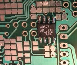
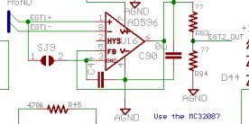
which resistors and capacitors to use? Very common to look up datasheet. I connected all grounds with wire (short a Cap-pads).
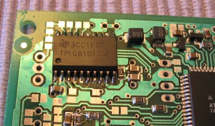
I've soldered for the TPIC8101DW knock interface chip: Some questionmarks here aswell.
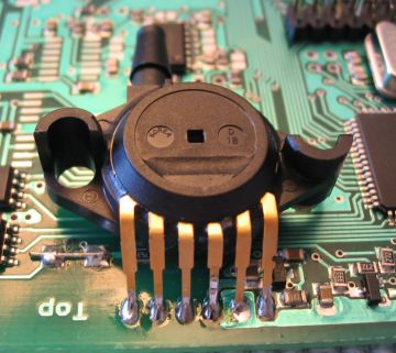
Soldered the MAP:
Next is prepare for the PIP signal from EDIS.
- D14 - SMD 5.1V zener (whats mounted there now? I'm afraid it's accidentally LL4148, a bug in the script for automated assembly that noone checked, and it was noticed later. It's not 5V1 zener. It doesn't hurt, but does not clamp at 5.1V. You can check by applying 5.2 .. 5.3V through a 10k resistor and see if it clamps or not. You can replace with a 5V1 zener, connect a 5v1 zener in parallel or connect a diode towards 5V.)
- SJ2 - Short
- SJ6 - Open
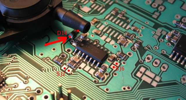
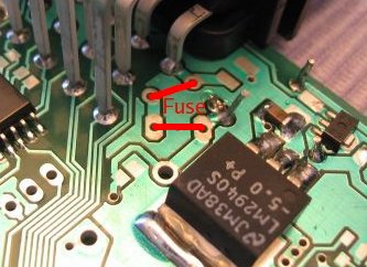
Is this the right way? How big fuse?
I think ether place can have a fuse. I used a 2A and put a Inductor on the other.
Are you going to use the stepper driver??
That is the only part that needs a lot of current.