I live in Burlington, Vermont USA. Just for fun, here's a link to a webcam near my house. http://www.hazecam.net/burlington.html
Personal car:
MembersPage/JasonRussell/MazdaRX7
My brother's car that is going turbo
MembersPage/JasonRussell/HondaDelSol
A rally/hillclimb car I installed and take care of
MembersPage/JasonRussell/SubaruSTi
Ultima CanAm Kit Car (efi small block Chevy)
MembersPage/JasonRussell/UltimaCanAm
ECU sent in to add Wheelspeed2 - problems
MembersPage/JasonRussell/JasonWheelSpeed2problems
1988 Mazda RX7 Turbo
Here is a picture of the crank angle sensor: Notice the 24 tooth wheel at the bottom(crank position) and the 2 tooth wheel at the top(of the Z axis). The 2 tooth wheel is the crank TDC (home position) for Rotor 1. This assembly turns at 1/2 crank speed like a distributor would hence it's 30 degrees of crank rotation per pulse with a seperate pulse for home position.

As for the coils, the Haltech guys use 4.5 - 5ms dwell time on the stock coils, so I figure I'll start there. The split trailing should be fairly easy. Although it will most likely require firmware changes (#ifdef ROTARY).
Visit my website for more info on my cars. http://www.6speed.org
I am starting to prepare for the install into my RX7. Here is a pic of a board with the way I populated the components. I describe below the pic.
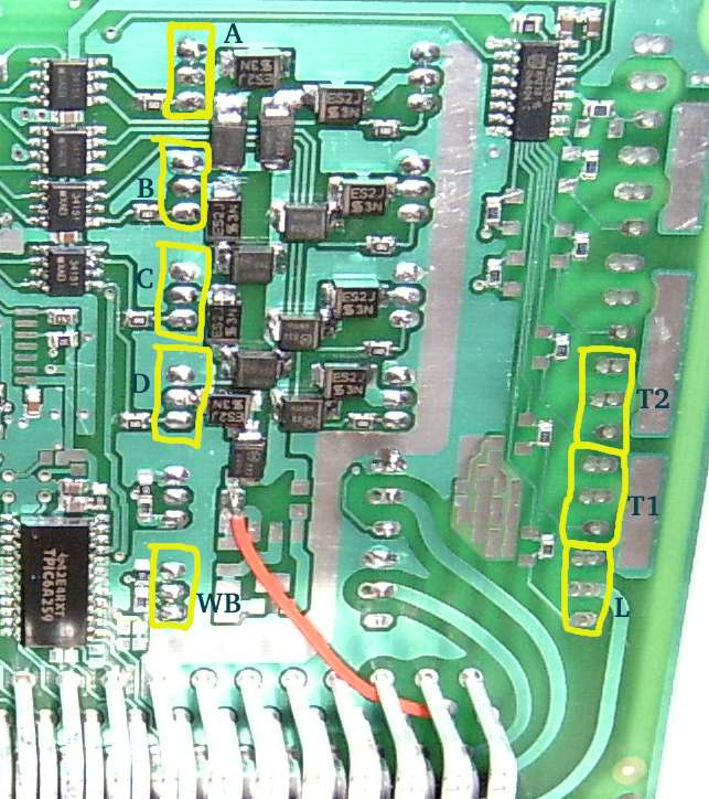
A = Rotor 1, primary Injector
B = Rotor 2, primary Injector
C = Rotor 1, secondary Injector
D = Rotor 2, secondary Injector
WB = Wideband switch of course
L = Wastespark coil for leading (bottom) sparkplugs
T1 = Coil driver for trailing (top) plug on rotor 1
T2 = Coil driver for trailing (top) plug on rotor 2
I'll be using both VR inputs for the above sensor, knock eventually... any additional suggestions?
Q: Where is the switch for the fan relay on v3? I don't see it on the EC pinout.
pick one (and we should definitely have some standard, so check the sch and check the code; code is quite flexible, eg. mik uses an ign259 channel, because he started his engine before he had TPIC6A259DW chip).
Q: What is recommended to use for the transient supression diode near the power supply?
U$5 is 1K5E18 or 22 (18 or 22V) throughole transient suppression diode, it's legs are very thick. It's in the rescue kit for some time now. Not a big problem if you don't mount it.
- This wasn't in either RescueKit you sent me with the 2 board pack. Not a problem. I'll buy a few and mount it later. I still have almost a month before the next race.
Q: Is there a predetermined use for JP1 (SDA/SCL) or are they free outputs? I'm trying to determine what pins to bring out to an external connector for future use.
A: These are free, they are wired to the I2C pins of the MCU and there is lots of useful I2C devices.
WBO2 test/setup
Here's the config on my controller now (this was used to make the wbo2logs posted)
wbo2_warmup_ramp=A0
wbo2_warmup_target=FF
wbo2_abs_limit=E4
wbo2_limit_maxt=A0
wbo2_fallback=60
wbo2_retry_t=06
wbo2_edgetime_corr=BA
wbo2_edgetime_min=50
wbo2_ri_target=96
wbo2_nernstdc_target=8D
wbo2_pump_pw_zero=65
wbo2_calibration=D0
wbo2_heater_pid_kp=46
wbo2_heater_pid_ki=10
wbo2_heater_pid_kd=1A
wbo2_heater_pid_ilimit=80
wbo2_pump_pid_kp=2E
wbo2_pump_pid_ki=1D
wbo2_pump_pid_kd=08
wbo2_pump_pid_ilimit=84
wbo2_ri_confidence_scale=80
Measured values:
- If the IN+ (pin3) is about 4V, and OUT (pin1) is close to +power (eg. 10..11V) than too much current is drawn by something loading pump-. You can make the 270 Ohm resistor (pin1 -> pin2) smaller but it worths to check where the current goes.
Solution: Put the 270 ohm resistor on the board. Works wonders. ;-) The GenBoard/Manual/WBSensorConnection page was misleading (saying they are all auto-placed) so I changed it for that component since all boards I have in stock are missing that R.
Here is a log I took tonight of a full warm-up. Any comments on this? (it's still greek to me)
http://www.vems.hu/files/MembersPage/JasonRussell/8_15_wbo2logs.tar.gz
This is broken!!
The documentation is lacking on finalizing the setup of the wbo2, so I hope changing that will help solving my own problems.