' Ethanol sensor firmware showing proper readings'
Given that the very common fuel flex sensor operations are known, VEMS should have a any trim for fuel, ignition and boost based on actual ethanol content (current way is to use a form of digital in wheel speed, which is too crude).
Many customers are extremely interested in this feature so it should be implemented as actual Ethanol fuel content adjustments.
MAT / TPS ignition retard should be MAP based, or configurable ( MAP or TPS )
Agreed, working on it (more work in VemsTune than in firmware).
TPS makes sense for engines that might not have MAP sensor at all. (ITB normally aspirated).
MAP is usually better and easier to tune.
So choosable is best.
I´d like to check how this is going on? - I meant the MAT/MAP ignition retard - Will this ever get implemented?
Input for Coolant temp and air temp can be selected from non pullup analog inputs - How?
This allows parallel installations to be done more easily.
ECU is setup for Cam sync but still runs if camsync fails.
- currently (~1.1.95 .. 1.1.96), with coil-type and extrapulse triggers, ignition continues even if camsync stops (just like the factory audi AAN)
- but ignition stops if measured camsync pos is outside the configured sectrig min angle and sectrig max angle, and event at bad trigger position=disable injection (which is not recommended unless one really knows what he is doing. The recommended default is "just show").
- with missing tooth (like 60-2) ignition stops if camsync fails
- should be improved to be user-definable behavior
This is easily handled by allowing configuration of outputs (ignition) in the dual config if camsync fails.
- no, not with the ign-outputs, but use sparkcut-revlimit !
- ign-outputs must not be changed with table-switching (because ign-outputs could possibly stuck in active state). But disabling ign by sparkcut-revlimit=0 is allowed.
Engine operations are not affected by the loss of camsync therefore.
- currently (1.1.96) the extrapulse seems to be the most userfriendly (like 120, 120, 120, 40, 80, 120, 120 campattern or 30, 30, 10,20, 30, 30, 30, 30, 30, 30, 30, 30, 30 crankpattern), because (while also supporting camshaft-angle-control) loss-of-camsync can be configured to either run or stop.
Right now fuelcut makes idle catch tuning tricky on some engines. How about a 'primepulse on fuel resume if TPS below IAC threshold, RPM falling, and fuelcut active'? Or something similar that allows for reloading the wall film when leaving fuelcut and descending quickly (out of gear) toward idle. In absence of proper X-tau some form of wall wetting would help with fuelcut recovery. Right now the only obvious solution is to richen the bottom row of the VE table and let EGOC take care of fixing those cells when cruising in those ranges. Even just a generic percentage of pulse width to add on fuelcut resume would work for most situations that I can think of, bonus points for having it scale against RPM or RPM drop/sec in some way.
camsync right at the missing tooth
sometimes before, sometimes after tooth0. (this is currently not allowed).
Especially important if cam angle is getting measured between 355-366 with a missing tooth wheel. Some BMW engines have the cam signal right in the missing tooth, this is a installation of the cam problem so some might trigger on one phase and some other ones on the other phase as well as some hopping between phases (which I have gotten, had to run dual out to solve).
Possible solution
- arbitrary internal camsyncpulse delay of X primarytrigger pulses
- i.e it sees the signal but waits to report it for 5 primary teeth or similar, VR sensor is used in this case and will be onwards
- yes, the proposed sheme makes sense. The other method would be similar to the "measure tooth" concept (used for the exhaust and intake camshaft-angle-control, but for the camsync it would be more complex internally and would require much care and intensive benchtesting of all trigger-setups at all conditions)
Idle fuel/ignition map.
Something like a 6x6 map that only is activated during idle condition (below rpm, below tps)
Y axis can be MAP or Idle control duty cycle, selectable between each no matter if main strategy is alpha-n or speed density
There is a VE(MAP,RPM) table. Splitting out a corner would add complications and worse, transients.
- However, using different axis in the different tables: VE(TPS, RPM) at the same time as multiplier(MAP, RPM) might makes sense (and it is possible already, right?)
- Sometimes ignition idle requirement is nowhere near what is needed at the same manifold pressure and engine speed.
This is done to get an even steadier idle without fluctations as well as low engine speed low throttle conditions which may require different ignition and fuel.
VE value resolution increase
At least a half a point or more
- 88-89 becomes 88.0 , 88.5 , 89.0
- DONE: 176, 177, 178
- just half reqfuel (you can tweak VT to display 88.5 instead of 177, but now much use).
Mass fuel option fuel table.
Ideally 0-Xms opening time curve that represents volume
multiplied by a factor for fuel density. Allow addition of fuel temperature compensation from analog input.
- anytrim already allows fuel pw compensation based on analog input
Especially important for low resolution pulsewidth when flow is non linear to have the curve and massive injectors.
Ecu then chooses the appropriate pulsewidth based on the curve from the mass wanted from the fuel table.
Anytrim by TPS
Can this be implemented as an option for Anytrim 1 and 3
Anytrim 3d
Allows 2 axis to be choosen from any analog channel at least and it´s axis based on that channel , preferably any reported channel. Would allow custom function tables whose effect can be any of the current functions or new ones added.
.. Yes this would be nice / Erikk
Improved boost control
Include the option for Secondary PWM Table Absolute as the base duty cycle table for the main boost control function.
So boost control would work so
DC table (kpa, rpm) + anytrim function + gearDCtable + PID = BoostDC
Then target can be altered by anytrim and TPS and gear table.
I believe this would give far improved targetting with high variances possible without having crazy PID values.
The tuning would be done without PID to reach the correct boost (kpa in the DCTable) in all rpms and alterations for various gears if needed.
.. New boost control strategy is under development / Erikk
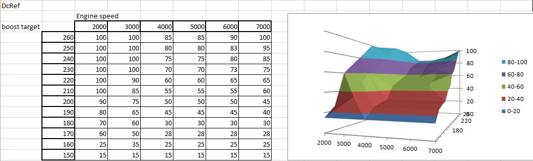
New idea for boost control (I have brought it up on the IRC already before) for highly improved targetting and converting the whole system into targetting, would of course work in simple style still.
New tables:
DCref table,
Y axis : boost target
X axis : rpm
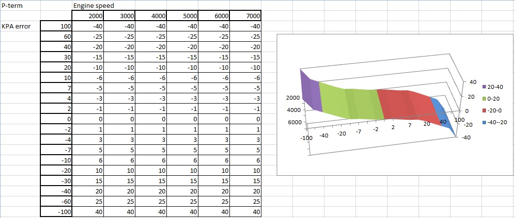
P_table :
Y axis : kpa error , target - map
X axis : rpm
Currently we have targetting based on
Gear, TPS and various other things. Irrespective of where the target comes from improved accuracy in getting to the target is needed when the boost target can vary from 150kpa to 300kpa or when wastegates have leaks or simply don´t behave smoothly or linearly.
My suggestion is that the user completes a 3d table which acts as the base DC for each scenario, i.e boost target and current engine speed, the way they fill it in is by adjusting the target and then adjust the DC "curve" throughout the engine speed range to get there or at least as very close as possible.
This by itself would yield probably 95% success rate in targetting later down the road for the user.
The PID then needs to act to finalize the DC%.
The best way I can think of it is rpm and error based 3d table which would allow the user to get the best possible control over correction at both the amount of error (unlinear P term at X rpm) as well as unlinear at Y error amount. So that absolute dc control is available and this should raise targetting succes to near 100% if done right.
I and D same as before, the variable P term and varying DCref table cover almost absolutely every scenario possible in terms of hitting the target.
- New boostcontrol is already being developed, should be here quite soon / Erikk
- to avoid P depending on the distance to the set point which is to rally (kPa error), one may add a feedforward term which is roughly the command which allows to steady at the set point. However PID terms could be scheduled by rpm /fphil
Antilag by Idle control valve
Would it be possible to add the function to run a specific idle control duty cycle while under antilag, thus acting as ALS valve.
.. Already implented, 'ALS Iac position' in the ALS menu / Erikk
Thanks for the heads up, - Gunni
A - B config
The current implementation I feel is wasting space by having absolutely EVERYTHING in each config.
My suggestion would be to follow the Pectel way.
Config swabbable things are things like
VE table, Ign table, Lambda table, boost targetting(gears, speed or whatever), variable cam target tables, Als configurables like rpm, duty cycles and such , not output pins or input pins.
Everything that is a fixed constant like ignition trigger settings, inputs and outputs wouldn´t change,
I believe this should free up some map space and might allow 3 configs to be swappable instead of 2.
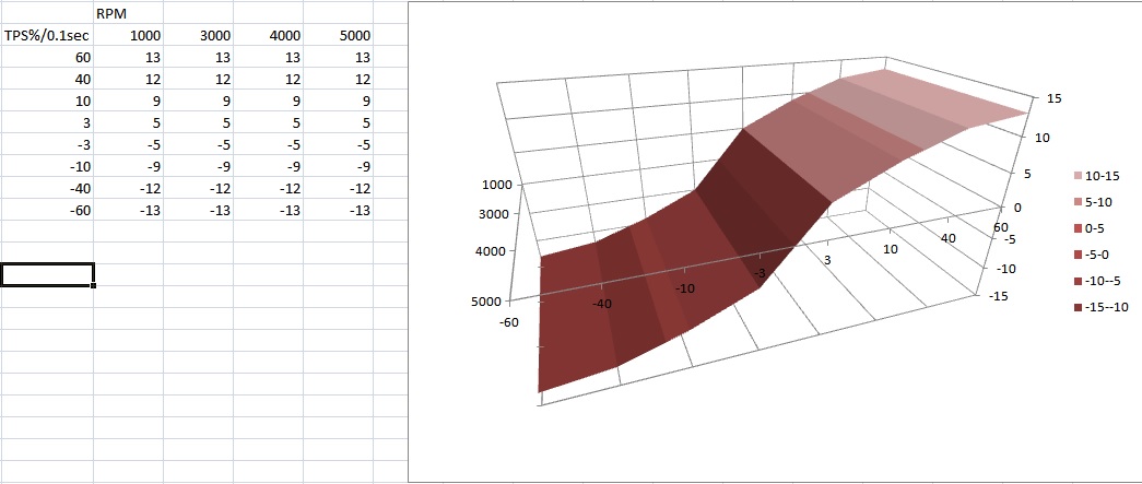
Some thougts on accel enrichment and deccel enleanment
I would propose a 3d table that has
X axis = dTPS% / 100ms
Y axis = RPM
Effectively combining the two curves available now.
Added addition to the 3d table is the option of having negative values on the X axis. Therefor allowing specific decel enleanment which would get subtracted from the pulsewidth.
The two values closest to the 0 would represent the deadband where fuel addition/reduction is OFF and closed loop and other things are active.
In addition the Cold multiplication factor is replaced by the warmup table effectively.
Below is a sample table
I want to reiterate this note.
It��s extremely common for MAP sensor signals to have time lag from actual airflow change into the engine
- can be due to hose length to the MAP sensor for instance or if the plenum has big volume.
- What happens is that the engine for no good reason goes rich when enleanment is required
- there is no proposed (or even known) algorithmic method to predict what the signal will be in the future
- in the ECU, or even in the universe there is no way around this
- delta TPS / delta T same as positive accel enrichment just enleanment - used by Bosch ECUs - I sent a link to a file that covers this a while ago in exact detail (page 401(6pages detail their method))
- amplifying D-term (differential signal) could help counteract a low-pass filter, but it amplifies noise extremely. No software can help if there is a time-lag (not a low-pass filtering)
- Maybe a MAP sensor close to the manifold (or connection with a sufficiently sized tube) helps ?
- obviously vemslog would be also required to evaluate any such situation (so that configuration can be reviewed, eg. that MAP filtering is effectively disabled in config (the processing of fresh MAP value and fuel pulsewidth recalc is extremely quick and efficient in VEMS firmware): it is possible to configure MAP sensor filtering that can act as low-pass).
- in the ECU, or even in the universe there is no way around this
- vemslog captured at high-baudrate (57600 or 115200) would be superior, and simultaneous scope-captured analog value from a MAP (really close to plenum, no filtering) would also help to see how the exactly described system behaves (tube length / diameter / connection / is there a small filter in MAP hose before the ECU... ?).
- note: the MPXH6400 / MPXH6300 series sensors are very quick, 1..2 msec (we haven't verified this but the Freescale datasheets are very reliable).
- There is an option to use TPSd/td as it closes to shorten the fuel pulse exactly the same as for accel enrichment, can be another table if its not possible to make the current positive delta/t table negative.
closed loop lambda EGO control
is OFF if lambda is > X Lambda
if OFF is lambda is < Y Lambda
These being adjustable if they are all ready in the firmware.
Allowing control over when to stop closed loop from adjusting PW when Lambda is outside certain values. EGO control is then 100%
MAP CORR is TPS CORR above X kpa, on some vehicles with RPM/TPS table there will be a discrepancy between the same KPA value at different throttle angles. Since MAP CORR is there it shouldn´t be difficult to turn that into TPS CORR above some kpa value.
note: MAP CORR was made for Alpha-N where the primary input is RPM/TPS anyway. (and adding RPM/TPS modifier for RPM/TPS primary table does not make sense).
- Use RPM / TPS primary table when needed (if different TPS for same MAP values need different fuel PW)
- and MAP CORR as adjustment (mostly used for boost, but configurable).
- What is means is that MAP CORR becomes TPS CORR for KPA load setup, TPS/RPM * MAP CORR is current , KPA/RPM * TPS CORR would be usable when load is KPA
Fuel injection timing modifiers
- Main axis is RPM (of course)
- is it possible to alter with anytrim ? (there are many many anytrim possibilities in VEMS, but the MAP based anytrim is not RPM dependent)
Proposal: Fuel injection timing needs a Y axis that represents load, either TPS or MAP based on load control selected.
With variable cam controls some modifier would be nice that can effect the timing requirements.
Fuel injection timing has noticable effect at low load: idle and cruising. At higher load most of the injection goes to closed valves (no matter how injection is timed), and at peak power injection timing has no effect at all (injector ON almost all the time).
Maybe a "Z" function (for each RPM value): 2 "RPM lines" table (interpolation between them of course => "smooth transition") would be justified.
- The Y axis could be cam-angle or MAP or load (which can be TPS/kPa).
- It is unlikely that anyone would ever provide measurement evidence (logs with power or smoothness records) about the usefulness, but it could be implemented.
- The Y axis is LOAD, that is how its usually done and makes the most sense, CAM timing can be put on hold
Both edges available on cam sync and other 720sync stuff
Is it possible to be able to report and use both rising and falling edges on Hall to show all trigger edges, then allow camsync to be a combination of using rising rising gaps or falling falling gaps or rising falling gaps or falling rising gaps or as currently selecting a cam event in relations to crank trigger ranges or positions.
would allow twice as many edges on todays cam triggers for more robust cam triggering.
Also as I've asked before a cam input delay in crank triggers, this would solve all my M50 cam sync issues as sometimes the trigger appears before the missing tooth and sometimes behind on other engines, having a X crank tooth delay would allow them all to have the same base config and it would be easier to support multiple customers.
Also would it be possible to be able to have cam sync on EC18-12 (3rd trigger) and have it reported as exhaust cam in the variable cam timing? Or EC36-13 and have that reported as exhaust cam to the variable cam timing ? This is isn´t a problem for dealers that do the install or understand what is going on, but for customers its not ideal having to explain that intake isn´t intake and exhaust is intake on SXX BMW engines.
Maybe it can be done via a bit in the config and Vemstune reports it differently to suit the bit value of 0 or 1? that wouldn´t need any firmware changes just vemstune work.
See Fuel pressure warning light: GenBoard/UnderDevelopment/RoundFirmWare