VR trigger fan noise
This page is about a strong (600W) PWM fan in a car, located in close proximity of the crank VR trigger:
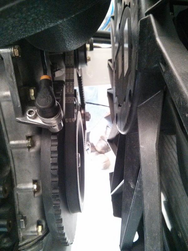
I've found the strange situation of VEMS starting fuel pumps and injectors with stopped and stand-still engine when the fan operates. Apparently the fans magnetic field is strong enough to trigger the crank VR signal-
Scope shot of this noise measured on VR signal cable:
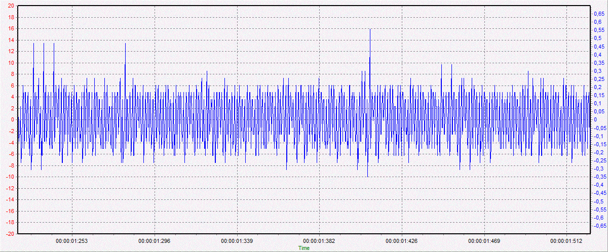
It's in the range of +-0.5V, more than enough for LM1815 triggering
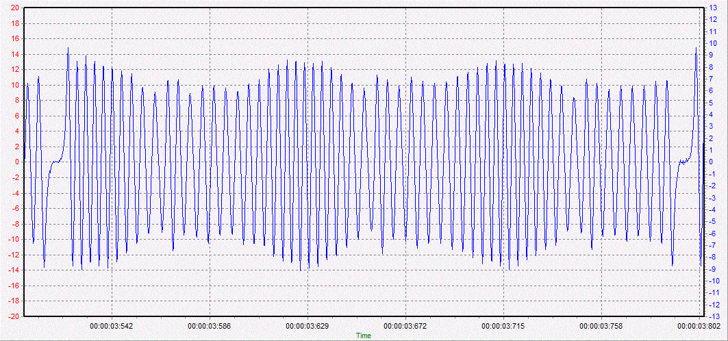
This is a normal scope trace of cranking the engine -without fan operating:
I'm looking for solution of this problem.
Since the signal/noise ratio is around 10/1, I've the idea to attenuate the VR signal with a series voltage divider at around 1:10 ratio.
[dnb] I too have seen this problem, but when headlamps are turned on or off with the engine not running. When the engine is running the LM1815 chip seems to be doing a good job suppressing noise so I am not too worried about the problem but a fix would be nice.
I am not convinced your attenuation idea will be completely successful - it might make the car hard to start when the VR signal is small at cranking speeds - but please keep us informed.
I have in the past used a 6dB "pi" attenuator so I can monitor crank triggers using a USB sound card (when trigger logging with VT was not available). It can be simply made with 3 resistors. I used the following to get impedances matching my requirements.
R1 = 13k1
R2 = 16k8
R3 = 3k6
Since the trigger is made of relatively low frequency sine waves, maybe an additional band pass filter could be built in to the front end? I suspect though that it all comes in at the same set of frequencies... It's difficult to tell without being able to look at an FFT of the data.
- Thanks for your response. Engine is running fine with the fan, but we need to use the fan even when the engine is stopped, and it was able to flood the cylinders in seconds this way. I've looked into a frequency-domain analysis of the noise but it's very even across the whole range. A bit stronger at very low (<100Hz) ranges. So the only freq. filtering I could do is the low pass filter to get what's above normal triggering (probably 8Khz?)
According to LM1815 datasheet, minimum signal is 150mV p-p, so attenuation of 1:10 leaves way over it, probably needs more to get the noise under threshold. (will try soon!)
[fphil] " Apparently the fans magnetic field " First I would search for the actual source of the noise. What happened if you shield your fans? Have you scope the relevant grounds?
Indeed the sensor shield can collect the electromagnetic field but then where is this shield ground? (if to the Vems, not a good idea)
- Thanks for your response. We've tried to put a big sheet of steel between the sensor and the fan with no visible change to noise. The noise has been measured at VEMS connector, just like the ground. Sensor cable is fully shielded and shield is connected to ground close to VEMS (this is the stock wiring and layout for BMW trigger cables and is working perfectly most of the times). The noise pick-up point is the sensor body itself, as it was very sensitive to the distance from the fan's motor, while the cable wasn't sensitive at all. We've tried a replacement sensor also (no difference). Perfect magnetic shielding of the fan motor or sensor seems very hard to me, probably it's easier to relocate the sensor down-under which had been tried manually and noise seemed minimal down there.
Still, I'd prefer to keep factory layout and teeth positions as long as possible -if I can resolve it with simple electronic filtering.
[fphil]You say that " big sheet of steel between the sensor and the fan with no visible change to noise" You have probably grounded the sheet. Indeed no effect against magnetic field
The frequencies are moving and it would be hard to set a filter which would work in any circumstances except you would build up an adaptive filter ;)
However as a last attempt to test if the noise comes from a magnetic field onto the head of the sensor or through the grounds, have you scoped the noise at that ground close to VEMS with regards to the battery minus, battery body ground? or put a big cable between both?
Besides I see no reason for the stock wiring to carry the noise of shield up to the Vems.
[GergelyLezsak]Update
I don't know much about shielding, but it is a common practice to connect shield to ground on one side only, to prevent current flow on the shielding. It's probably easier to find a good ground on ECU-side than on the sensor-side. This prevent possible DC offset between grounds also.
Anyway, problem seems to be solved by simple attenuator as planned, a 10/1 voltage divider.
Layout: sensor_signal - -> 10kOhm - -> VEMS_VR_IN - -> 1kOhm - -> GND