Injector measurement
I was interested in injector opening/closing time, flow regarding to flyback setups.
NEWS 2007.04.04
I've done a measurement of a full set of six (Holley) 55lbs injectors (mentioned earlier also).
Here's the flow comparison chart.
Full details in XLS here: http://quasar.dynaweb.hu/~lezsi/vems/holleyX6.xls
Higher-than-spec flow values in low pw measurements are probably caused by slow closing time. (So f.e. at 1ms the injector was open for ~1.5ms instead of 1ms which was the base of calculation)
I'm not sure is it good or bad. How it will affect idle quality?
For example at 1.2ms it would be 15% difference in flow between the slowest and the fastest injectors, that means lambda value of 0.92 for one cyl. and 1.07 for the other (biased at 1), which is usually quite a big difference...
2007.02.05
Previous measurements were obviously inaccurate, so I started over with better equipment:
It's now the "what we've expected" chart, linear, with some degradation in flow at low pw values.
I started with the smallest possible pulse (which actually made the injector open). Holley is low imp, so it's faster to open/close. It needed almost 50% pwm duty at 11.5V battery, otherwise it couldn't stay open.
Still seeking the answer to the question: Why we couldn't get stable idle with lower than 3ms with the Accel inj above? (And why it's using 90% duty to feed ~300 horses on a 6cyl/6inj engine?)
- Reasons might be many. Maybe an AFR is a too much on a rich side and spark advance (seems to be 21 deg at max) few degrees too little. At least if datalog link below reflect your settings.
- it's a bit more stable now, at ~1100 rpm idle which seems a bit high (for 6 cyl!), but injectors like it and luckily it's not a daily driver...-maybe it's inj. deviance @ low pw..
- Similar engine, with 7.5:1 geometric compression ratio, ported head, std camshaft and 0.65-0.69 kg/cm2 boost delivered 203 Kw/400 Nm. Injectors used are Bosch EV6 four hole design, 261 g/min (about 350 cc/min). http://www.vems.hu/wiki/index.php?page=MembersPage%2FBengtR
- max. ignition advance is around 28-29 deg at 0.7 kg/cm2. Min lambda 0,84-0,85 and max. injector duty around 58 %.
2007.01.26
I did some measurements with setting cranking RPM range high. Basically it worked fine, but two problems arised:
1. Pulsewidth simply disappears (goes to zero) after some amount of time. Time's between ~40-120 seconds of "cranking". Sometimes it doesn't need to have RPM signal at all just change settings in megatune, and pw on LCD/megatune/in_reality changes to 0000. Switching off/on resolves the problem for the next ~100 seconds.
2. Above 20ms of cranking pw, scale changes to 0.5 msec (so 20.0 + 55*0.5 = 47.5 msec can be specified at max: rarely needed, but it is by design). Above 25.5 msec, megatune displays pw - 25.6 msec.
About the results:
I'm not sure whether this is normal or not. I expected a linear growth of flow with pulsewidth (at least in the higher range).
- Results are certainly somewhat wrong. Did you measure actual pulse width. Measuring opening time with oscilloscope or graphical multimeter etc. would clarify measurements. //BengtR
All of the above pulsewidth values includes all timing (I have set all open times to 0)
2007.01.22
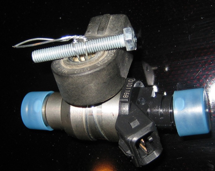
I've put together a flowbench-setup
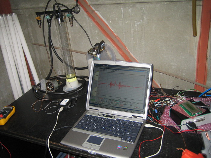
First tests showed that injector opening time increased slightly according to the fuel pressure introduced (3 bars). No flow measurement data yet.
Question: How can I force GenBoard to a specific pulsewidth?
-Tried "mxofemxofemxp05mxp05" and similar, but no effect at all.
I would use a soundcard ElectronicDesign/TriggerSignalGenerator with 60-2 or similar pattern, and use "cranking RPM" (both low-temp and high-temp values set to same pulsewidth). you can bump up cranking_thresh, but best to apply 290 RPM or similar. Take care (and have multiple fire extinguishers at hand). -It good-and-working idea, thanks.
- You might want to measure (if measuring 'acutal' flow rate) at around 6000 1/min (ie. 100 Hz) or similar (depending your engine maximum revolutions etc.) and around 80-85 % opening time (ie. 8,0-8,5 ms at 100 Hz). //BengtR
- Good idea, I'll check it later, first I'm interested in the idle-area.
All of the below measurements made on a 12 Ohm Hi-Z injector dry -without fuel pressure-, and PowerFlyback installed inside the ECU. No PWM-ing was enabled, pulse width is ~14ms.
Voltage was 12.1-12.2V, voltage/current measurements were made after a 0.3Ohms resistance, so test setup is like:
+12.2V____[0.3Ohms]____*Measurement*____[injector]____INJ-OUT
The results:
Red channel means measurement voltage (or current).
Blue channel means mechanical movement/noise.
- 1. graph is one open-hold-close pulse with no external flyback. Closing time is 1.7ms
- 2. graph is similar open-hold-close pulse with 18V Zener flyback. Closing time is ~0.95ms
- 3. graph is similar open-hold-close pulse with 30V transient diode flyback. Closing time is 0.9ms
It's visible on the red channel that after opening (about 1ms later) current has a pulsation which shows the movement of injector iron core. At the same time mechanical noise started (blue channel).
At closing phase there's not visible current-pulse in red channel but a spike goes well over starting (+12V) voltage which is the inductive "kick-back" or flyback current. Blue channel's mechanical noise shows here the exact position of mechanical injector closing.
As my movement/noise detection (knock sensor) was nearly installed on the injector it's coil slightly picked up injector current, so on the blue channel it's also visible when injector current switched on/off (a single spike before noise).