Trigger output
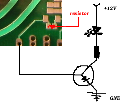
What's the most sane way to check that ignition works as it's supposed to? I don't want to install expensive IGBTs on this development board, so I wondered if pulling a signal cable from the bottom hole for the IGBTs to a NPN transistor which controlled a LED would be a good idea? Would this work? If not, what's the /easiest/ way to accomplish this?
HALL: (done)
Trigger1:
Pin is connected to IC by 10k R55 and shorted SJ2.
It's protected by a 5.1V zener on D14 and a short on D13.
Trigger2:
Pin is connected to IC by 10k R91 and shorted SJ5.
It's protected by a 5.1V zener on D27 and short on D24.
The signal should look like this 'hall signal -> pulled up by 10k to 5v -> 10k series resistor -> 5v1 zener to ground -> ic1 pin'. Thanks, Dave.
Schematic diagram showing the recommended hall setup
![[hall schematic diagram]](http://www.vems.hu/files/DaveBrul/mini_hall.JPG)