1.1.90 First check & How to install the 2nd VR Trigger?
First check of Version 1.1.90 with Maserati option
I uploaded Version 1.1.90 on my genboard (SerialNumber = v3.3_n001201) bought in 2005.
The config file is 2011.04.22-19-58-49.vemscfg
VemsTune is 0.10.84 (2010.11.15)without the configlet Maserati Z012 and trigger play Z012. I was unable to find how to download the last April version.
Results by using my Maserati.biturbo.wav :
- Does not start, of course Camsync cannot work: my second trigger is Hall. Needs conversion to VR.
- camsync disabled -> full start FINE
How to install the 2nd VR Trigger?
I have to install an LM1815 to get secondary VR trig.
I first followed the document named "Genboard v3 Official build and test guide" 2.2.5 and soldered the LM1815 component and as fixed the blob and the wire (appendix 4.1 on page 18).
I also check the GenBoard/Manual/InputTriggerHardWare. But the 1st reference was simplier to follow as a start. This is what I got:
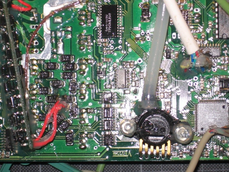
I should have also read check the sectrig options in [shop]
- currently sectrig=VR (now not same as auditrigger!!!), EC36pin13 is setup for VR input. EC18pin12 is an mcp3208 input
- the masking signal is pulled up with 2k7 to +5V internally
- earlier the 3-input (1 primary + 2 signal for secondary) auditrigger (without camHALL inverter): EC36/13 was the masking signal (if not pulled to ground, but left the internal pullup to pull to 5V - resulting voltage should be 3.5V or higher)
- than the VR input (earlier EC18/12) was used only
I did a short test to see if I can get a full start -> Bad: Same result than before.
|If you split your MembersPage/FPhil page thematically (see MembersPage/DavidBlades for a good example) and agree to continue documenting the wiring and config you use (also thematically) shop grants you an assembled ECU free-of-charge with VR/VR, write in the order comment "MembersPage/FPhil offer by Marcell 2011-04-29".
Vems note: Secondary trigger VR overview
The LM1815 circuit for the secondary trigger is same as for the primary trigger, which is built according to the LM1815 datasheet recommendations.
Since the sectrig pulsecount is lower (it never has to cope with the 135 tooth 10000 RPM auditrigger), higher capacitance can be applied in the filtering and the output timing circuit as well.
The LM1815 keeps the output pulled down to 0V, and releases for appr 50 usec (t=appr RC from R and C values) after the zero crossing negative-going edge on the input.
- The LM1815 output design is a bit weird! Inverted output would have been saner ! (for lower supply-current and better measurability) but that's how they made it.
- also, with the inverted output, the LM1815 output blob (on the bottom side of genboard) would not be necessary, the LM1815 would not disturb HALL signal.
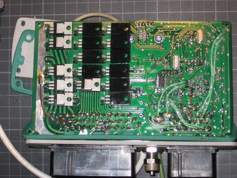
- But the LM1815 (otherwise a good chip) works this way, and with VR setup the LM1815pin12 output must be connected to microcontroller input pin (SJ7 solder-blob on the bottom close, to the line of FETs). With HALL setup it must NOT be connected.
Vems note: VemsTune generated maserati trigger signal
In recent (eg. 2011-04-26) VemsTune, Tools/Play trigger, type in "z012" or "Z012"
- even if not added to the combo selection, you can easily type in using the keyboard
- The difference between lowercase z and capital Z is polarity.
The sound-card is often sensitive with low-toothcount signals. So with ECU connected, verify in Tools/Analyze Trigger that the signal seen by ECU is same. Might need to play with mixer volume. Also, disable any 3D effects !
Firmware 1.1.90 full start
After by unsuccessful test after the 2nd trig install Marcell noted:
- R182 on LM1815 pin7 was missing so the peak detector circuit for adaptive hysteresis was not connected,
- pin 5 should better be connected to the 5V pad (midpin of SJ4) in orde to set the LM1815 ine mode 2(arming threshold fixed at 200mv) and
- to solder a 1k pull down resistor from the input line to lower the line noise.
Also I realized that even doing so, this would not have made my 2nd VR trigger to work since I input the signal through EC38 pin!! Actually, it should be input from EC18 pin 12 since my board was ordered in 2005 with 2nd Trigger Hall.
Hereafter is what I finally done (May 6 2011):
- Updating VemsTune for the good April 2011 version. Now the Play Trigger Tool works for "z012" option.
- R182 set as a wire, mode 5 selected, signal given from my .Wav file, Firmware 1.1.90, 2nd trigger camsync enable
- with 2nd trigger disable
- Same results with z012 signal.
- Same result with a square signal from generator whatever the voltage level.
- Testing the pins of the LM1815
| pin2 | GND | ok |
| pin3 | Vin | ok |
| pin5 | 5V | ok |
| pin7 | PDC | 1.6M to GND ok |
| pin8 | VCC | 5V ok |
| pin12 | Ref. Pulse OUT | 0V!! KO |
| pin14 | RC Timing | Pulse is 5V-0V-5V ok |
- Comparing these results with those obtained from the LM1815 for Trigger1. For that LM1815, Pin12 Ref. Pulse OUT is good: it gives a 0-5V pulse at the negative-going zero crossing of the input signal. The width is 0.25 ms. This pulse width is given by the resistor capacitor circuit at pin14 which circuit is the same than for Trig2 LM1815.
- Testing with pin5 opened (Mode 1) or grounded (Mode 3)These modes are to fix the upgoing threshold before any peak adaptation
- Testing the GATED OUTPUT pin10 with pin11=0 and pind9=0
- grrr !!!
- Let see the downstream circuit connected at pin12. What is this C103 capacitor made for?? Is it to better and low down the rising front of the pulse !? This could be too slow. Oh yes wiki is saying something about it: C103 should be removed or made smaller, such is done for the board shipped after 2005 (from 2005?? not mine?)
- Taking out C103
-> Firmware 1.1.90 running with camsync enable on z012 or .WAV input signal!!
-> LEDs lightening when current driven through EC36 pin 11 or 12.
I did not have time to further on and to find the menus options to get proper firing for this odd fire coil type configuration.
May 22
I got the firmware running with the actual trigger pulses picked from the car.
I also noticed that the negative side of the cam pulse was shorted to -0.6V. This is not the case for the pulse generated by the .wav amp. The output impedance for the sensor is quite high: 600 Ohm and there should remain on the genboard some diode set from the 2nd trigger Hall input.
I only have a notebook from the 90's (256kB!!) and was only able to run MegaTune. Here after part of the log file:
| Time | RPM | Engine |
| 285.862 | 0 | 11 |
| 285.948 | 10 | 11 |
| 286.089 | 226 | 11 |
| 286.210 | 265 | 11 |
| 286.314 | 388 | 11 |
| 286.418 | 527 | 13 |
| 286.560 | 671 | 141 |
| 286.701 | 570 | 141 |
| 286.823 | 591 | 141 |
| 286.945 | 578 | 141 |
| 287.031 | 652 | 141 |
| 287.153 | 703 | 141 |
| 287.312 | 696 | 141 |
| 287.455 | 759 | 141 |
| 287.616 | 849 | 141 |
Anyway we can see that genboard starts to run while the engine is still cranking, which is a good point.
I feared that because genboard firmware 1.1.90 has to find out the smaller side between the 2 triggers to sync, - which means at least a full cycle of cranking, the genboard start would take too long. This is not the case.