Ignition Introduction
As a starting point, I tried to use Alien logging via the secondary trigger to learn what the dizzy actually does. This wasn't very successful due to a couple of factors...
- Alien logging was broken in the firmware I am using. I got something working, but I don't trust it all that much...
- The vac advance on the TVR distributor is not all that sensible - it has a delay in it, meaning that a given RPM and manifold pressure is not enough to say what the total advance should be.
| RPM | 1000 | 2000 | 3000 | 4000 | 5000 | 6000 |
| Advance | 8 | 14 | 20 | 26 | 27 | 28 |
I do have an approximate ignition map from this, based purely on RPM which will do to start with. I will then apply "vac advance" as required during mapping. The new scheme should prove much more successful than the original system. (I will eventually get the car to do more than 20 miles to the gallon on local roads, even if I have to push it!!)
First cut ignition map
[Add table]
Ignition Hardware and Wiring
I have ordered 8 coilpacks from http://www.034motorsport.com/ in the USA.
Possibly worth thinking about stocking them in the webshop for those of us who don't have coilpacks in the car as standard? Even with tax and stuff paid, they should only cost 50 euros or so. (Maybe less if they're bulk ordered.)
The first job is to get some brackets made up to support the coils. They will be placed on the left hand rocker cover, as this is the only flat space I have left in the engine bay! (The right hand side will be used for the twin throttlebody plenum)
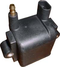
Coils test assembled:

I hope to get the brackets machined from aluminium this week.
This didn't happen, so I had to resort to plan B - making them out of what I could buy from the local DIY store.
Brackets on the engine:

It won't look too bad when all the wires are arranged neatly.
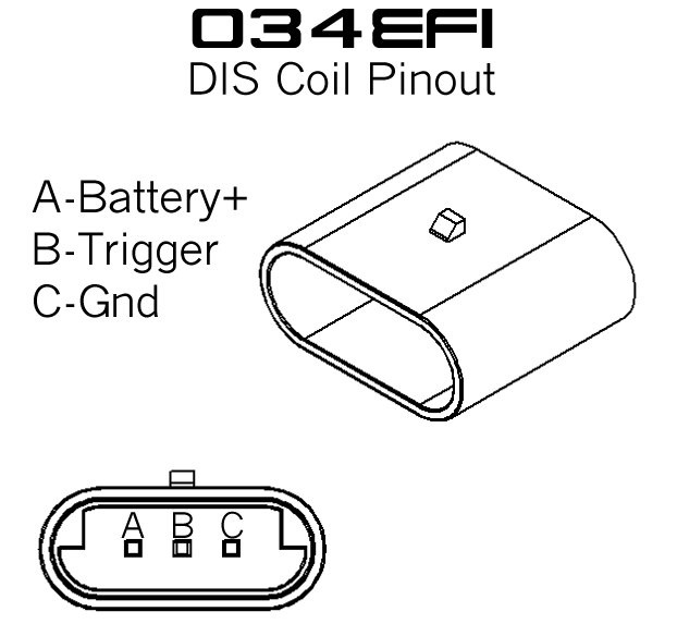
Coil Polarity
There is a turret for the HT lead and a 3 pin connector on the coil. The 3 pin connector contains ground for the secondary and both the primary connections.
No wiring instructions were supplied, so coil polarity will be worked out by either guessuing or applying a step change of voltage to the secondary and seeing which way the primary voltage moves... It does make a difference if the polarities are correct - the centre of the plug electrode should be +ve wrt the engine block. Q Is this correct?
Yes, spark polarity matters. I didn't found the article I read this so
- google: positive spark polarity ground engine sparkplug
- a [snippet]: the breakdown voltage is increased by about 30% for the plug with the positive polarity on the center electrode. What does this mean? One, our ignition system has to be able to come up with this extra juice, and two, on two cylinders your center electrodes will show wear while the other two will show it on the ground strap
The supplier has sorted out the polarity for me with the aid of a nice diagram... All done now.
Configuration
Not too much to say here. The coils are just coils, so it's dummy ignition using the 8 IGBTs. Then there's just the coil dwell and firing order - same as injectors but stepped round the cycle half way - to set up for this.
I've entered a dwell of 3ms for the moment, and will see how the car responds. I suspect that it will be sufficient as it is - the sparks look much better than the old coil and dizzy gave!
The complicated bit will be getting the cam trigger to work, but that's another section.
I found a very useful keyboard command to test fire the plugs with the engine off:
mdnxx - where xx is the h[2] cell number (07 down to 00). I used this to test all of my coils by manually firing 8 plugs sat on the plenum and it all seems to work.
Misfire detection
With the advent of the new firmwares (Currently using 1.1.66, but I have worked in this idea on and off since 1.1.4x) there is the possibility of creating a misfire detection algorithm.
I have made a first attempt at this in order to diagnose an intermittant low RPM misfire I seem to have on my test car.
The algorithm I devised uses the "rtestN" columns from the CSV datalogs.
Q How is this tooth timing data calculated? And are there any funnies in it relating to missing teeth and sample timings that I might need to account for?
This chart shows the standard deviation of the tooth times divided by RPM plotted against RPM. We see that there is considerably more deviation when the RPM is low, implying either there could be a low RPM misfire OR the cam is wild and there is simply a lot of "noise" - charge robbing and the like causing weak combustion. The spread of data at low RPM is to my mind more consistant with an intermittant misfire than simple bad cam behaviour.

Here we see a histogram of the standard deviation of the tooth timings. Note that the distribution appears to be Weibull (possibly even Rayleigh) with a long tail of long tooth timings, implying that I can consider this tail to contain all the misfires.

This shows a datalog done on a dyno with a section of deliberate misfires. The MAD_spark line shows my misfire detector being triggered.

Once I know how the tooth timing data is sampled, I will be able to work out some more useful stuff.
Back to MembersPage/DavidBlades