Assembling the Ver.3.2 GenBoard...
Followed MembersPage/JohanEriksson/VerThreeFirmForDummies
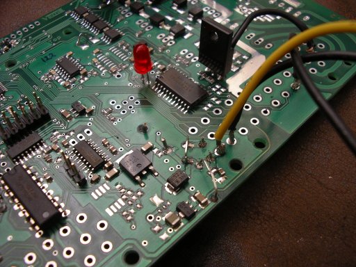
Q:: did i forgot some parts can't find the problem messured 12v, and 5v on HALL sensor supply, sp2 nessured 12v on 2 pins i think i need to solder more parts but have no clue wich should be added.
![[Next picture]](http://www.vems.hu/files/MembersPage/Daihard/img/gen2.jpg)
Notes:
- I recommend to solder the flyback wire to the middle of the flyback trace (so 4 diodes are on one side, and 4 on the other). This results in less heat on the flyback trace (25%) when max 8*1A flyback current flows at a low-impedance setup. For highz it doesn't matter.
- make sure the TO220 switches (FETs, IGBTs) do not break off due to vibration. The GenBoard/VerThree/CaseAndMounting is more durable considering bibrations.
- make sure the IGBTs don't contact each other.
![[Picture link]](http://www.vems.hu/files/MembersPage/Daihard/img/gen3.jpg)
![[Picture link]](http://www.vems.hu/files/MembersPage/Daihard/img/gen4.jpg)
08-05-2005
fitted the board in to a alubox and fitted separate connectors for:
LCD - DB9
PS/2 - keyboard
audio jack - serial communication
Neutrix 4 pole - WBO2
Neutrix 2 pole - EGT
Need to fit Chinch connector for Knock coax cable
Need to fit Din 4-5 pole for 3 step steppermotor.[closed,1,2,3 staged open]
24-10-2004
Its working soldered a variable resistor between pin 1 and 3 at the LCD didn't know its that important and thought soldering them as the final touch :) thx...
Made the ps2 connection all LED's on the keyboard lightning up on powerup so asume these work aswell. Now starting to check the board with MenuHardwareDebug.
23-10-2004
I'm trying to get the LCD working checked the wiring its ok
I'm using a old pc IDE cable even got about 5volts on the nr connection but the lCD isn't showing any sign of live
- the LCD is enabled by default
- the board is tested OK with my own LCD
- the LCD display itself is not tested by me, but it comes tested from the distributor and very unlikely to be faulty
- as you didn't talk about squares (that appear when the LCD gets supply and the contrast setting is OK), you either didn't get the GND and 5V right or ( more likely ) you didn't connect contrast. The proper way is to apply a (say 2k7) variable resistor and tune to max contrast, but most often a 270 Ohm to GND is just perfect. (besides the 270 Ohm to GND, also connect a 2k7 to +5V or -8V if the 270 Ohm to GND is not enough by itself).
using the following pins and lcd connection
Processor side
LCD 1 - 13 - 11 - 6 - 2
genB_LCD X - 2 - 4 - 6 - 8 - 10
genB_LCD X - 1 - 3 - 5 - 7 - 9
LCD 4 - 14 - 12 - 5 - - [blank] => X not used
Econoseal side
I'm not going to match this table to GenBoard/BuildProcedures/LCDconnect
22-10-2004
Its ALIVE (resoldered the LED to misc position )
my RS232 cable as good as i could and got a Blinkping and DATA connection YEAHHH :) So now further to step 2:
- Testing mdh..
- Connecting the sensors
- Testing sensor inputs for functioning
- uploading firmware via BootLoader to the processor
- More testing
16-10-2004.
After reading and reading the site,things are going alot better'
evry thing is fragmentated but hopping from item to item will get me there :).
1) Injection 3 HighZ injectors so need to solder 3 FET's and 3 smb diodes from the resquekit with the stripes facing eachother then soldring the 3 FET's.
Well do that tommorow..
2) Well did the soldering today almost finished...
Power: F1 Big black thing in.
C72 1uF; D45 KE 22A C101;
temp: R9 and R10 2,49K
HALL: R55 10 k + SJ2
Ignition: IGBT 3x Q3,Q6,Q9
Injection: FET's 3x Q1,Q2,Q5 and 3diode's Mo 016LV HighZ setup; and Flyback wire
EGT: C44 271ohm; SJ9 and AD597
Knock: C17 10nf
WBO²: Q18 FET.
Stepper: D45 (done with power) and SN754410NE. No need for the 8 flyback diode when SN754410NE is used (it has them internally).There is not even place for them since v3.2.
Hmm, powered the board up but no response, found that the V+ to the stepper was blocked through D$5 diode removed this and fitted a wire bridge on 2 places ie F1 and the bridge to the stepper driver. Also got 5v on the HALL sensor output connection,
still LCD not working as the Blinkping.
Stepperdriver: Soldered C76 and C75
Power: removed D45 replaced with 2 wires.
http://www.vems.hu/index.php?page=MembersPage%2FJohanMo
I don't fully get the current state of your setup. I added some notes to GenBoard/VerThree/Testing (best to have RS232 working first).
Dave noticed:
LED doesnt blink because it's in the wrong position: mounted at CL instead of MISC
Helpful links
Main Build handout just follow this:
- BuildProcedures/SectionThree
- Pinout FET's GenBoard/Manual/InitialTesting/VerThree
- resistor values: KinderGarden/Components
- Injectors Flyback schema: GenBoard/Manual/DDFlyback
- Rescuekit easy for identifing GenBoard/VerThree/RescueKit (eg. capacitors values)
Duplication of GenBoard/Manual/InitialTesting/VerThree
- Big electric drawing printout png (png is unsearchable, unlike pdf)
- Parts identifing list: http://www.vems.hu/files/genboardv3/megasquirtavr.pnp
- Top parts positioning:http://www.vems.hu/vems.hu/files/genboardv3/v32top_r244.pdf
- Bottum Parts positioning:http://www.vems.hu/vems.hu/files/genboardv3/v32_botchips.pdf