Stock opel X20xev
primary trigger 60-2 HALL effect
Scope measure from stock ecu:
1V/Div
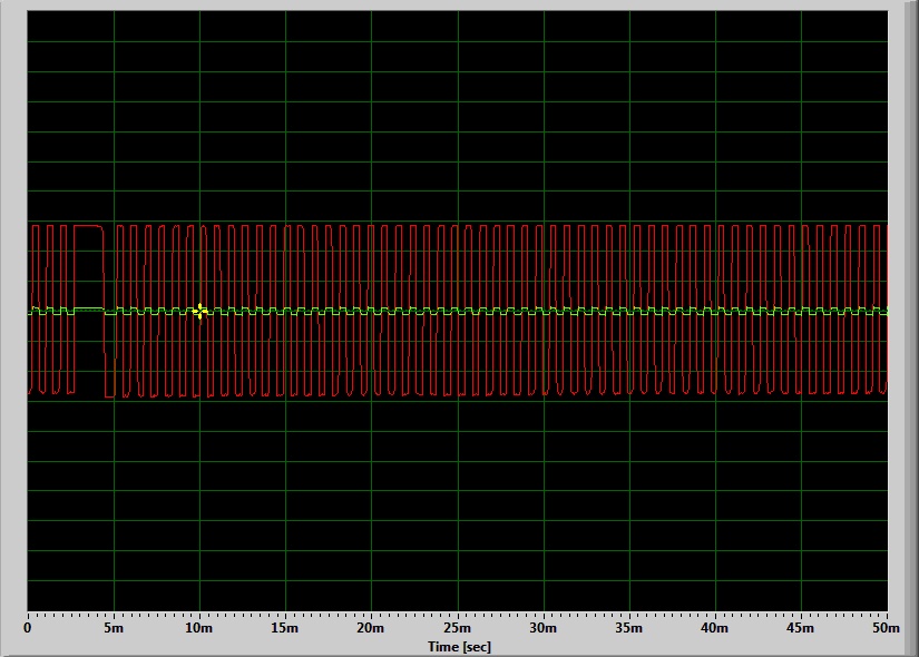
Soundcard trigger played m582 with trigger errors. (but soundcard is rather like a VR signal, and it might not be proper for HALL input... For HALL input: negative voltage is not recommended at all)
between ec36 pin 26 and pin 27 162 mV measured: it should be >4V in the other phase. (in gear 5 move the car slowly and watch with DVM).
sj2 closed sj6 open R30=3300 ohm parallel with 27000
according to GenBoard/Manual/InputTriggerHardWare that's OK.
The stock hall sensor is 14.4 volt supply
Do I need any changes???
With the v3 connected to the sensor there is no signal.
- Measured with scope ?
- EC36/pin27 should measure appr 4 .. 5.2 V when the sensor is disconnected.
- try to pull down the EC36/pin27 signal with 1kOhm instead of sensor
- or with VemsTune ?
- that can be caused by misconfiguration also. In VemsTune, check validate ("check icon"). Check configuration carefully
- [error reporting] step 1-2 almost done (this page)... Step 3-4 is exactly what should follow: upload vemslog and triggerlog
Measured with scope and vemstune. The triggerlog is empty because its no signal from the hall sensor. The config is validated, its the default 4 cyl 60-2 no cam sync Trigger edge is Falling.
The parallel resistors defining the disconected voltage on pin 27? (sould I put 1k instead of 3.3k?)
If there is no pullup in pin27 then the sensor is not making signals?
If only the scope is connected to the sensor and the supply there is now signal. (Plug the stock ecu then trigger is there )
When the stock ecu is connected ignition on mesured 182 mv on sensor conector.
Car is running, repleaced hall effect sensor with vr. Trigger hardware reconfigurated.
http://www.vems.hu/files/CsotiF/v3.3_u009043-2014.11.08-18.22.39.vemslog
Q: How to set ve table over 255 kpa?? or fuel cut over 255??
A: First save you current config; then In VT->Base setup->Ecu Calibrations->Table kpa Unit = 2 (>250 kpa). Restart VT, reupload your config. And everything should be sorted.
Best regards, Dave
I did as you said nothing happened. My default table unit was already 2. Tried 1, 2, 4, no change. Restarted the vems every time.
- not sure what is happening there, but max 1020 is possible, and upto 510kPa is possible with the (default 2kPa config resolution).
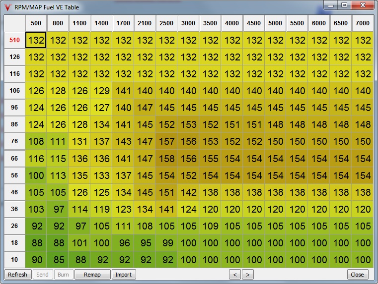
We even updated the screenshot at the bottom of the [VemsTune HELP] using your [vemscfg], just the bins were changed to max 510kPa. You can easily verify that the VE values are of yours:
- j[0]=5A 55 58 5C 5C 5C 5C 64 64 64 64 64 64 64 64 64
- j[D]=84 84 84 84 84 84 84 84 84 84 84 84 84 84 84 84
- As you can see, it works. (corner values, in this case: 0x5A=90 0x64=100 0x84=132 )
- Use newest vems.hu/vt (and update ini from web)
The same time if I enable ALS for a switch what is working for Launch nothing happend (disabled launch that time).
- we tested many times, used in thousand installs, and we know certainly: ALS also works if configured correctly
- note that in a vemslog (not just .vemscfg) one would show "at ... sec mcp3208 input N ... is activated by pulling to near 0V, and although configured as ALS input switch it does not ... Although I expect ... to happen, it's ... instead".
- with sg like that, we could understand what you expect exactly and why it's not happening and most likely we could point to the right dir
- See [VT error reporting] and [generic info on reporting]
Not sure what was the problem but updateing to 1.2.30 solved the problem thanks for the help.
VR-type Speed sensor input hardware (HALL sensor should not need signal conditioning).
I want to use the ABS wheel sensor for wheel speed input.
- Only info I'm finding of this is: " VR signal and a simple NPN inverter (same as CamHALLInverter?) can be used to drive the signal (LM1815 is not necessary for this, although that would work too). Care is still needed of course."
- So NPN converter: The inverter can be an NPN transistor such as TIP31 or BC817 (almost any NPN transistor that can handle 10mA and 20V) emitter (gnd) connected to ground (EC36pin26) collector (output) connected to ECU cam-HALL input which is EC36/13 if the inverter is outside the box or the PCB side of the cut EC36/13 pin if the inverter is inside the box or an onboard pad on v3.6 2k7 .. max 10k pullup resistor between +5V (EC36pin28 or pin29) and NPN base HALL sensor output connected to NPN base. which is NOT EC36/13 if the inverter is outside the box! just the base pin of the chosen transistor the connector side of the cut EC36/13 pin if the inverter is inside the box EC36/13 pin on v3.6
Q: I put the 4k7 resistor and the zener make the NPN converter and I'm ready to connect the wheelsensor?
- VR sensor (or soundcard) -
4k7 resistor-- NPN base- 75k pullup resistor between NPN base and +5V
- 5/(75000/4700 + 1) = 0.3V bias, so appr 0.3V signal threshold almost always reached and triggers (but might be sensitive to noise also)
- NPN collector connected to ECU wheelspeed input signal (or HALL trigger input, but for trigger even more care is needed so this is only recommended for soundcard benchtests)
The [VR to HALL adapter] is preferred.
- good signal can be made with NPN inverter, but requires your knowledge in that case. (measurements, distinguishing good operation, ...)
- When ordering ECU, (or if ordered earlier) request an NPN inverter in webshop order comment (no extra charge).
Q: If my idle valve is opening suddenly like when I relase the clutch without any throttle my map goes up suddenly and it is lean because my idle valve lets in the air just like if I step on the throttle but there is no enrichment for idle movement how can I compensate that? Or can I make an Idle movement enrichment table?
Q: If I drive I have constant speed and load and I decrease the TPS just a little the engine goes rich because the map decrease. In the other way when map increase without TPS I go lean. Can I make a compensation if map goes up without tps to add req fuel and if map goes down deract req fuel?