I have just get a set of diy vems 3.7 and I was a little bit confused not to find any up to date doc for this so I decided to make my own.
MembersPage/CsotiF/Genboardassembly/Buildingdocs
So if you are building the v3.7 this is my way to get it done:
1st step. -prepare
Read the offical guide and Lezsi's guide under building docs.
2nd step. -the list
Make your own list of part what you have ordered or you will order and make sure each one what is it for.
For example mine:
1 x GenBoard v3.6
1 x Alubos EC frontplate
- Drill-count: 0
1 x Alubos Endplate
1 x Alubos gasket
1 x Alubos1600
- Drill-count: 0
1 x Bare MAP sensor
- MAP connection: sawtooth
- Pressure range: 400 kPa
- Supply: 5V
6 x Ignition driver
10 x Injector or WBO2 heater driver FET
1 x Idle stepper motor driver
1 x Ignition driver insulator sheet
- Size: 3lines
1 x Econoseal18-PCB
1 x EGT amplifier chip
1 x Econoseal36-PCB
1 x Dual channel knock sensor interface
2 x K-compensational cable (20cm)
3rd step.
First of all, get the flyback wire in place because after installing EC36 it's little bit hard.
The Flyback is the 2nd most important thing to get right under building v3.7 (1st is GROUND) So if you chech the pcb you will see two hols at EC36 pin23. That is because you can install the flyback wire there so stick a 1 mm2 wire in the hole closer to the side of the pcb.
Shown as here:
1.0
.jpg)
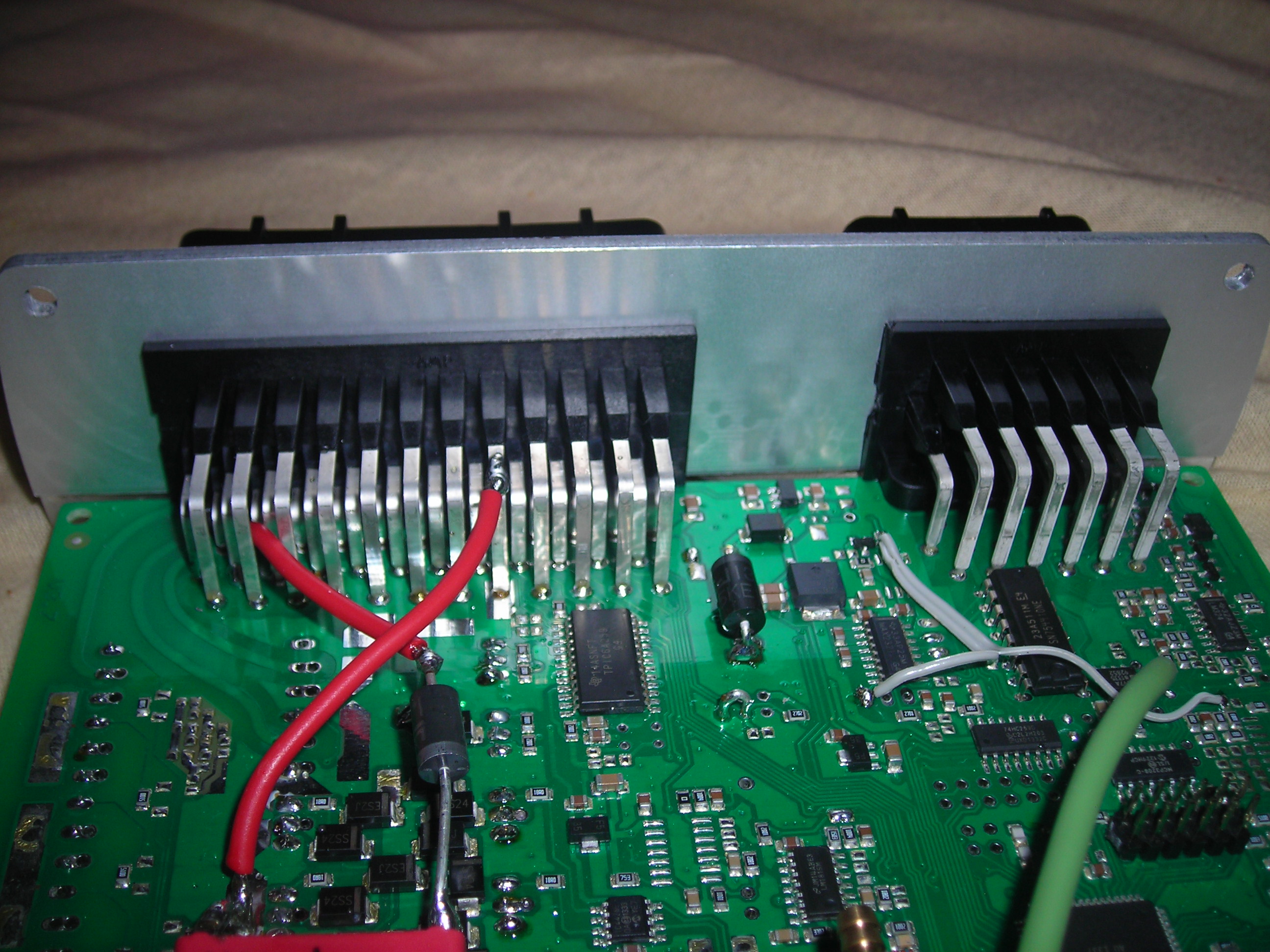
Then you can install EC36 and EC18 connector. But before you solder on it make sure to get the exact 90 degree angle and the alubos plate to have it on is nice also.
The result will be:
1.1
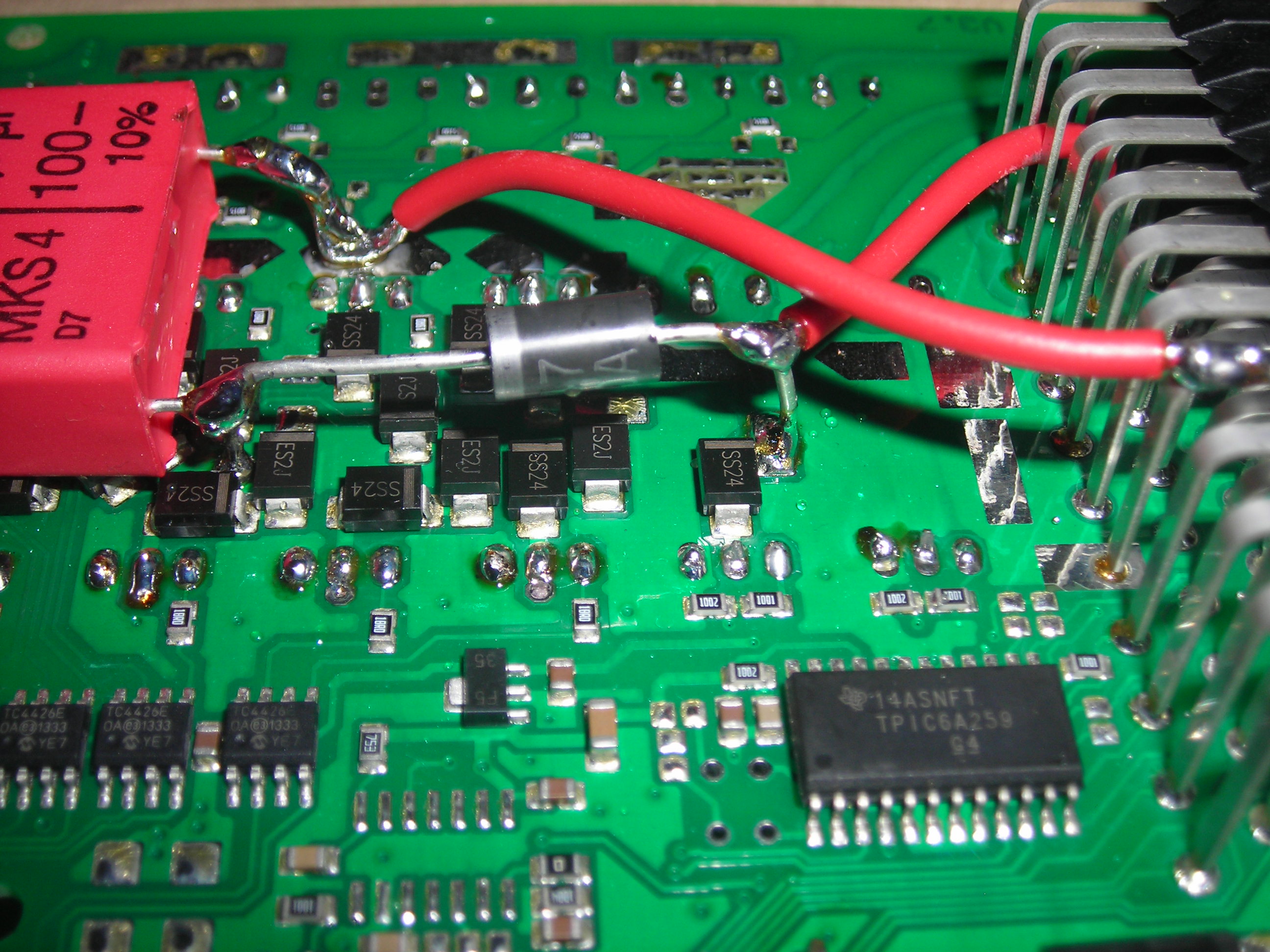
Now you can install the flyback it self. I use a 30V basic 2 diode flyback. It's comes with the genboard so it's free you don't have to worry about buying it.
This two picture shows the hole thing:
1.2
1.3
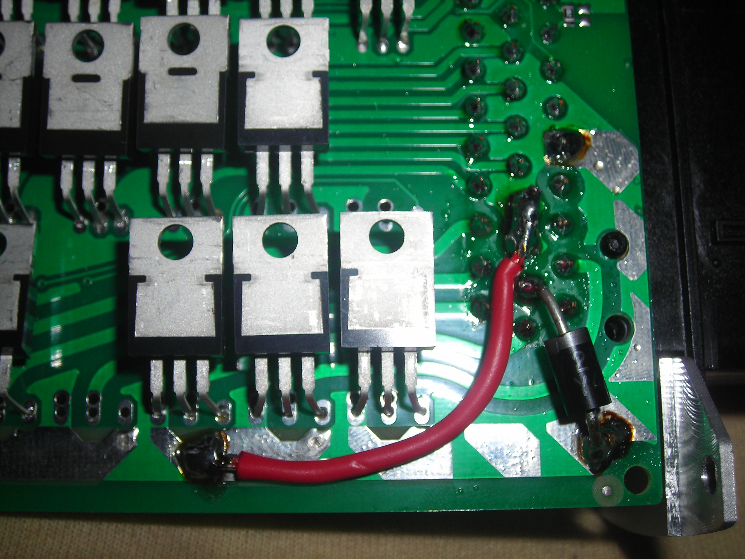
To make sure the upper image shows the 1.5KE30A and lower image is BY299 and make sure the negative side is in the right place.
This is important thing what you must install!!! Otherwise you can blow your fet't and your engine.
Ground reinforcement
This is the most important thing!!!
Because the pcb can't take infinite current you have to help out. So the picture above (1.3) has a ride wire to reinforce the IGBT's ground, use lot of solder.
The other one is in pic 1.2, the upper red wire goes from EC36 pin5 to injectors common ground.
Know the communication and analog inputs
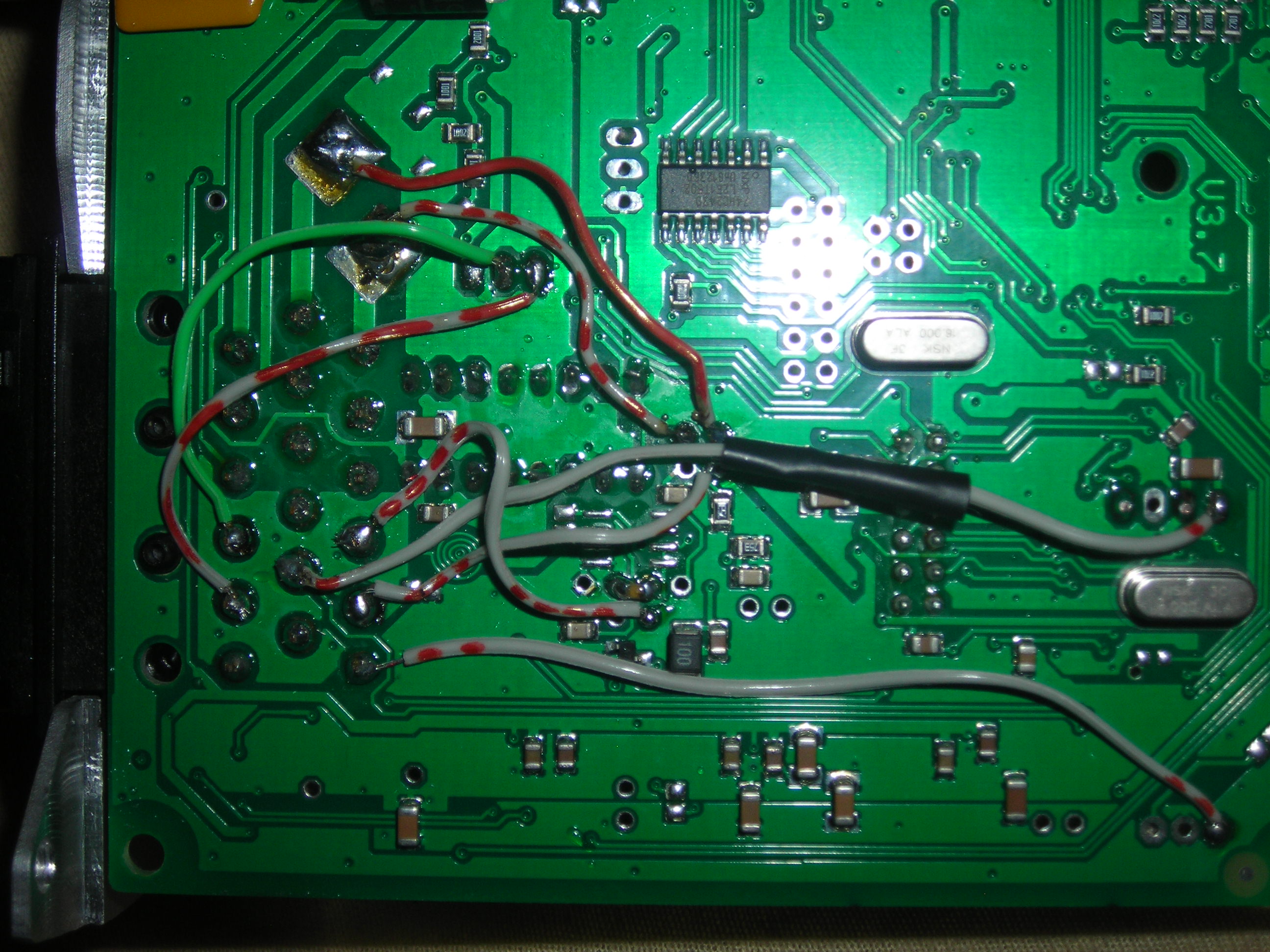
Under the black tube is a 2.7 kohm 1/4 watt resistor
For further information see Lezsi's guide under buildingdocs
Other things you have to install:
This diode is a 1.5KE18A
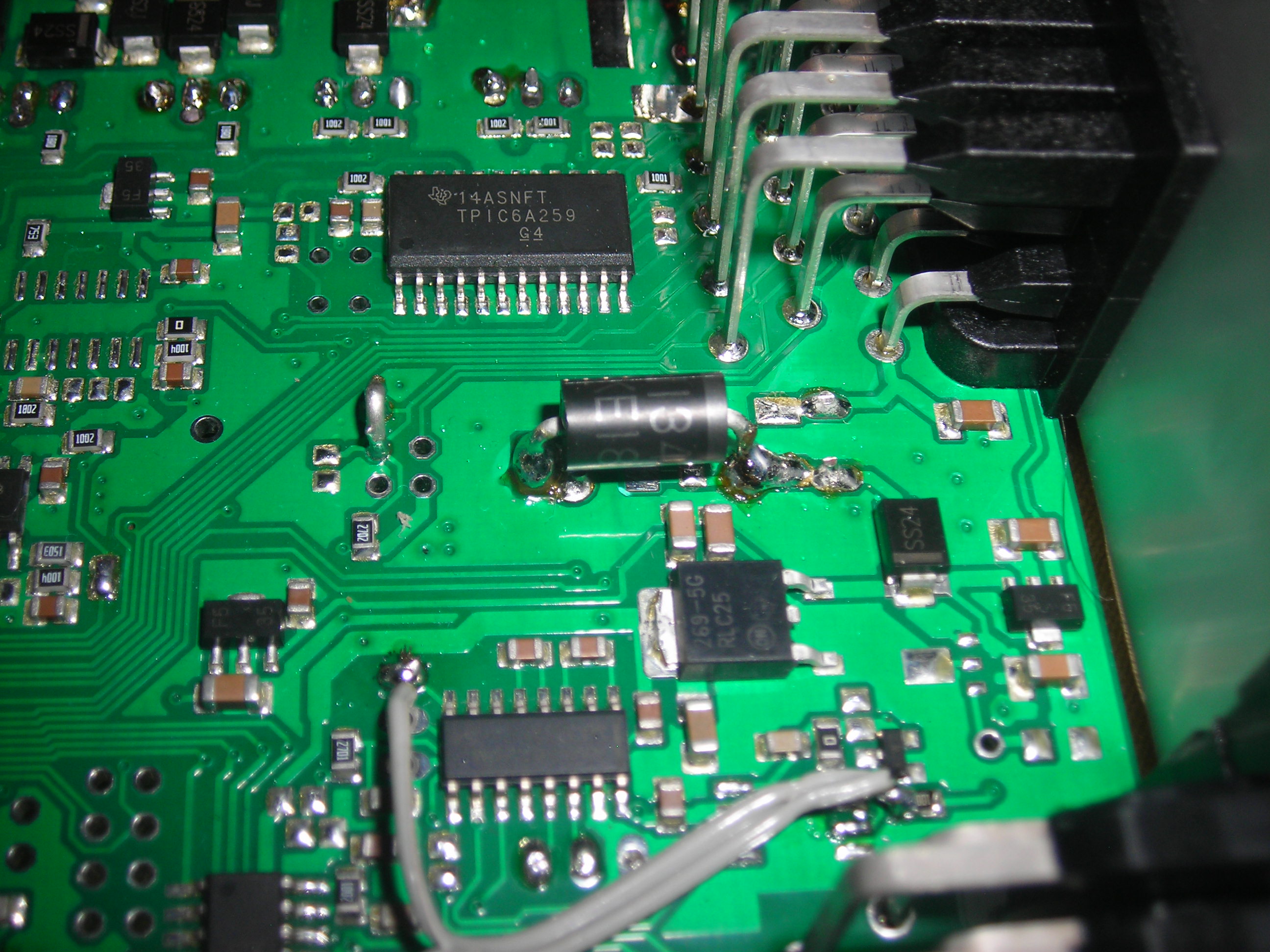
This pic also shows the ad597 for egt and the wire orientacion also.
This pic shows the knock sensor orientacion and the 5.1 zener diode if you are useing knock detection
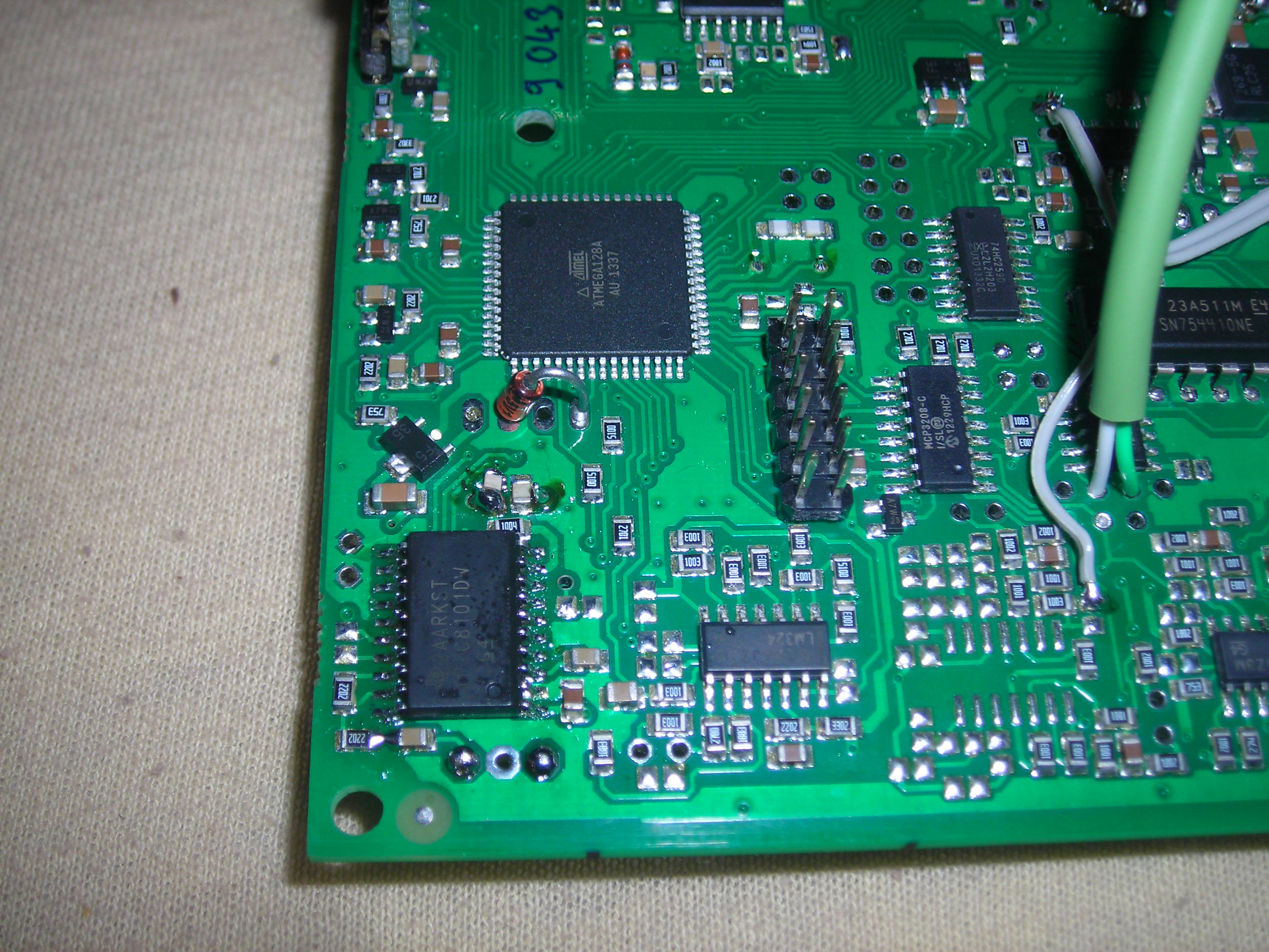
And you have to install oscillator
The lower one.
At last you can install the FETs and IGBTs as it's clearly discribed in offical giude.