Hi
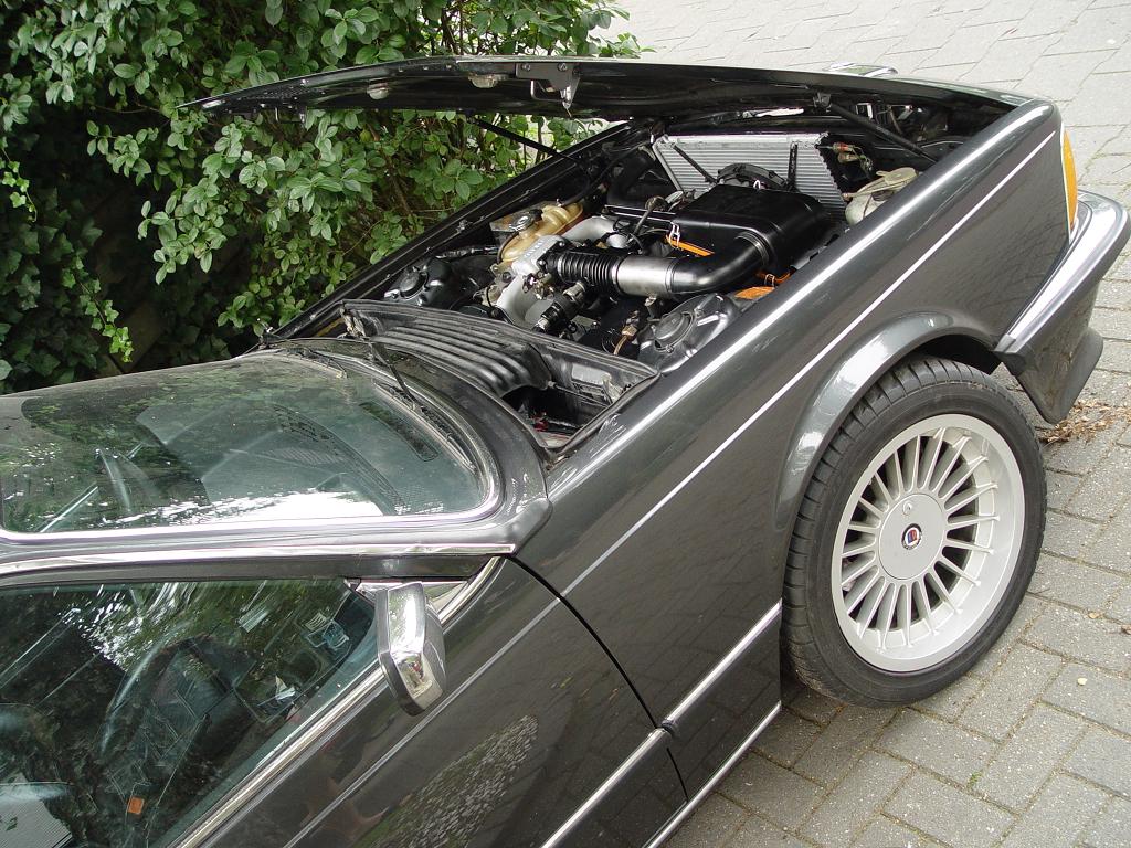
I am working on a BMW 635 csi '79
I am going full sequential ignition and injection in the future but for now wasted spark is OK.
All hardware is ready now only camsync not. For now I want to run wasted spark using COPs. But the inject and ignition outputs are a mystery for me.
Q1 I read I need to configure ign_dualout but I cant find where??
A1 I asssume you are running the latest released firmware/megatune package ? If not, get it from [here] (unzip and run megatune) then if you take a look at settings -> ignition settings, you'll find the option "Dual output mode"; enable that. After that set up the ignition channels in settings -> Ignition outputs dual setting screen. - DB
Verification of setting
After setting it, you can verify by doing a Man mcd dump in TerminalProgram 9600,8n1 (exit MegaTune while doing this) that ign_out=72 (not 70, that is normal dummy-ignition).
The mcd and mct are the standard canonical dump of firmware variables. The information as suggested on IssueReports is the recommended way to document settings, it allows easy reproduction of setup, quick review by experts (which increases your chance to catch config errors if your setup intentions and wiring is also documented) and avoids any human error or MegaTune problem (using very old version that is incompatible with recent firmware, or MegaTune bug). You can use MegaTune screendump for spectacularity, but mcd, mct dump is also highly recommended.\n
global.h describes variables:
uint8_t ign_out;     // EDIS:0x0? dummy: 0x7? disable:0xff bit1: ign_dual_out bit0: invertout
EGT
Q In the beginning I tested the egt when vems was not yet installed everything was fine and I had a nice reading. But when Vems is installed it doesn’t work anymore most of the time it says 0 en than for a msec 150 C and 300 C en than 0 again.
- I have 2 egt channels but only one sensor and both channels give the same readings
- you can connect a sensor to both inputs simultaneously
- I tested the sensor with an multimeter designed for Thermo Koppel’s and works fine!
- what sensor do you use ? Is that surely shielded ? That is the + and - has no galvanic connection to shield (>1 M Ohm). The WebShop EGT sensor is this type
- normal DVM can meausre
- disconnect the EGT (both pins) and apply an alligator clip on the wires (or short with some other mean). Heat this shorted end to >+10C (with your fingers) to see if reading is > 0C
New info: when the sensor is completely disconected megatune give the same readings (for a msec 150 C and 300 C en than 0 again).
Wiring
ignition outputs
Pair 1
Coil 1 to pin 35
Coil 6 to pin 33
Pair 2
Coil 2 to pin 11
Coil 5 to pin 12
Pair 3
Coil 3 to pin 34
Coil 4 to pin 36
when using the keyboard command mdnxx, I get a 2 nice sparks for all 3 pairs
I'm now testing the ignition coils and al work well with keyboard command mdnxx. but when I crank the engine nothing happens even the spark advance in megatune stays red ad the background en says -1.7 degrees
Q2 What is wrong please see my config
A2 I guess you dont see rpm while cranking either (or irratic rpm numbers) it seems you have your trigger tooth and another trigger tooth swapped in config. Since you have a 60-2 on a 6 cylinder, another trigger tooth should be 60 / 3 = 20 (14 hex) trigger tooth should be adjusted so that ign_tdc_delay is around 60 degrees. (6 is usually a good starting point) - DB
Q3 The rpm number is good now but stil no spark while cranking
A3 your ign_out is set to 0x02, that should be 0x72 (DUMMY ignition + ignition_dual_out) easily adjusted from megatune->ignition settings->ignition driver type: DUMMY. (verify config afterwards) - DB
The input triggers: original 60-2 wheel (BMW e34 ’90)
Camsync: [Hall-Effect Vane sensor]
Camsync sensor position with the info on GenBoard/Manual/InputTriggerCamSync
I made the following drawing to figure out where the camsync must be placed
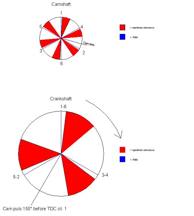
So if i turn the crankshaft to 150 degrees before TDC of cilinder 1 the Hall sensor mounted on the camshaft should give a reset puls.
Please correct me if I'm wrong
RPM GAUGE CONNECTION
I want to connect the rpm gauge and followed the directions from this webstore page: [inductor]
I don't completely understand it so i made a drawing

Q Can someone confirm that I understand it correctly and that this is the correct way to connect the inductor.
See DocsPage bottom for file area to upload images.
alternatively you can upload the pictures from your computer to another image hosting ("gallery") site like [http://tinypic.com , than copy and paste the url for the image into you wiki page.