22-09-2017
New Genboard v.3.8b SN: 15516 Homemade:
Bootloader Problem: After assembling the Genboard (AAN/Auditrigger), i tested the VEMS just with GND and 12V+ connected, nothing more connected. All runs normal and i load my config file. After the config,i start to load newest firmware, during upload comes a fault message and the upload broke up.
I disconnected the power and restart the board. I used my old RS232/USB adapter with FTDI chip and after the restart it was no more able to connect with the board. I tested the new Adapter with profilic chip and with this one it was possible to connected again. VEMStune says the board is in the bootloader mode. If i want to leave the bootloader mode, its not possiple and comes the message "Stay reason: Bad marker (0x34)". I tryed to upload a lot different firmwares, but after 0,2% allways it brokes up with the message "Firmware upload has been cancelled". I reset the board with a jumper set between DSUB9 pin 2+3, but no help.
____________________________________________________________________________________________________________________________
I build a new AAN Genboard V3.8, with Hall/Hall setup.
For ignition I want to use 5 Logic Level Outputs
- I connect the gate withe the output and soldered a second 510 Ohm resistor parallel to the other 510 Ohm resistor.
- sounds good
- If i measure now the Logic Level Outputs, than i have all the time 2,5V
- sounds like some PWM-ing is configured and it oscillates between 0V and 5V (DVM showing "mean" / average value)
- and in the Ignition Test Mode, the Voltage jumps only from 2,5v to 2,7V.
- It is possible that i destroy the 74HC259 Chip?
- yes, possible.
- Try to disable ignouts first (in config), and configure misc2 to ignch0 / ignch0 inverted (switch back and forth: that is a very good test you can easily do with a DVM!)
- The ignout pulses are VERY short, you cannot measure with DVM (you can see on a scope if properly using the scope advanced triggering features: you can see on a LED connected between output and GND, with 270 Ohm series resistor => much easier )
Solved!!! Now i used a scope for Testing. On the end i found a weak GND wire inside the car loom.


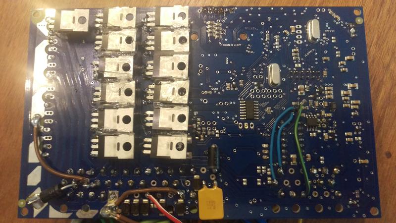
Home build AAN from Genboard v3
Soldering:
Reenforce soldering on TO-220 componets's GNDs, they really weak at this time.
IAC:
A shottkey diode will need from JPT55/4 (EC36/6) to the flyback JPT55/37, cathode face to JPT55/37 (Solder the diode's cathode to the anode of the 30V flyback diode, this is the easiest way.)
Ignition:
Remove all FET witch is in the place of an IGBT and solder an 510Ohm(1206) parallel with the soldered 510Ohm(0805). After this connect the gate with the output in the place of the removed TO-220 component.(Wire the signal from the two resistor to the Econoseal pin.) You need to do this only on outputs used for ignition.
Insulating:
Stick the teflon sheets to the metal case, this way the components will insulate from the case as well as from each other. In the end recommended to make insulation test with a lamp. Connect one pin of the lamp or anode of a led to +12V, other pin or cathode to the metal case. Start to test the injector outputs in VemsTune one by one. If the lamp or led ever lights up, the insulation is bad. You need to fix it.
WBO2: If you not reuse or add wires to the factory harness, it won't work as it connected now.
Both of the controllers has factory AAN configuration, if you ever miss them up you can download or we can send you.
Note that since 2015, there exists dedicated VEMS "v3.9" mainboard for Audi AAN motronic55 harness pinout. It's cleaner install for any mot55 harness (but it has no stepper chip, and fits in longer box: AAN PCB is 110*160mm instead of 98*160mm). Otherwise same (hw, firmware, sw) as genboard v3.8
- the midopa (middle LM2902 or LM224, labelled LM324 on schematic) is NOT needed, and NOT populated, it's only useful in very special setups (differential input). (could be used to amplify non-GND referenced signal, or to amplify non-insulated K-thermocouple signal).