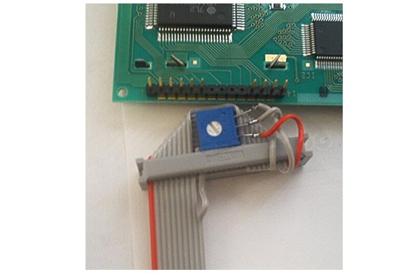
This picture shows the LCD end of the cable. As the picture shows, I have glued a pot to the connector to make the LCD bias voltage. Another thought I had was to instead put the pot on the ECU board right behind the 10 pin connector. The IDC connector is a dual row connector and you need to (obviously) plug it in the correct way. To polarize the connector I removed the 4 unused pins from the pin wafer. I then took the 4 pins and cut them in half. These pin pieces were then inserted into the unused holes of the dual row connector to make the correct connection the only connection possible.
I don't have a scanner to post my drawing of the connector in the picture. :-(
Below is the pinout of the 10 pin connector at the other end of the cable shown in the picture. Those 10 pin headers are available with polarized shrouds to keep polarity correct on that end too.\n
 Signal     10 Pin Header
 name       pin #
 ------     -------------
  gnd        1
  lb7        2
  +5V        3
  lb6        4
  biasV      5
  lb5        6
  lcd_rs     7
  lb4        8
  lcd_ddir   9
  lcd_en     10
-Dana
Non destructive connector - without soldering to LCD
Jason (or others), I see that you test LCDs before sending out from WebShop. What connector do you use? Is it made from a 5.25" floppy cable ?
Something like this should be available in the right size but these can be modified in a pinch. http://www.elfa.se/elfa-bin/dyndok.pl?lang=en&vat=0&dok=148034.htm