Runout
Some factors can impact VR trigger quality.
The amplitude of tooth pulses is not equal
This is a common error with homemade trigger wheels that have a long deep gap at the missing tooth (this results in a higher amplitude around the missing tooth). Professional wheels have a continuous depth-change at the missing tooth, full depth is only reached at the middle. Examine a 60-2 Bosch wheel.
triggerwheel is not centered on the shaft
Sine wave will modulate the VR signal amplitude, so the arming threshold becomes important, especially at high RPM.
If in doubt, record VR signal with scope or your notebook soundcard.
Unzip and play: [generated soundfile with severe runout]
Variation in individual tooth-height just makes the problem worse. Mik was the first to experience such problem when he patched his original (quite exotic) 18-1 + 18-1 crankwheel with a surgery for normal 36-1 tooth. The added tooth had smaller amplitude than the original teeth.
- in case of "serious wheel runout" (systematic amplitude variations within 1 rotation), eg. at 2300 RPM R37=100k..270k (or 150..360k in parallel with the 1M) instead of the 1M resistor can help the LM1815pin7 "forget the amplitude" faster. (so the primtrig VR R37*C38 gets shorter, C38=220nF)
Noise suppression: Adaptive hysteresis is designed to suppress eg. 1000mV noise at 1500mV signal amplitude, but still allow sensing a 240mV signal during cranking (yes, smaller than the suppressed noise at higher RPM).
- Easy to see that the otherwise awesome adaptive hysteresis does not work well with severe runout problem
- this is one case where a naiv trigger detection without noise suppression works better (although more sensitive to noise from other sources)
- or the adaptive hysteresis needs to be (at least partially) suppressed, eg. with lower R37 (and/or higher R181) resistance
Soundcard can be used to record VR signal
See ElectronicDesign/SoundRecorder for better description
WhatEverYouDoYouDoItAtYourOwnRisk !!! (take care of your soundcard)
- voltage divider with 10..22k and 1k resistors
- series cap > 100nF (220nF is perfect. Optional, since soundcards have internal cap, but it doesn't hurt to have one just to be safe)
Since the VR signal amplitude can be quite high (especially at high-RPM, often >30V), the line-in input should be preferred to the mic-input. With mic-level input a much higher divider can be used, eg. 100k and 1k.
- Some playing with the mixer is always needed to get a wav with desired amplitude
- at idle the signal must stay below 20..30% amplitude variation so it stays within limits at high-RPM.
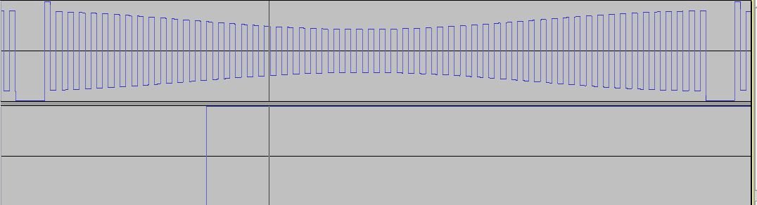
Example problematic wheel signal

Note that this signal is inverted because of the soundcard. It was verified with other means that v3.x sees proper signal polarity (either with InputTrigger/TriggerLog, or the engine does not even start with the other VR polarity). Here we focus on the amplitude problems.
shows that
- too high amplitude at the missing tooth
- because of the troublesome "missing tooth" implementation instead of the "missing gap" (or elonged gap). The magnetic flux at the middle of the naive missing tooth is lower than at other teeth, that's why the signal is bigger (remember: the signal is the rate of change of the magnetic flux: dFi/dt). The [fixed wheel] should cure this. Also, the fixed wheel is more balanced mechanically. The [new waveform]. Unfortunately still not good
- amplitude varies a lot between normal teeth as well
- likely because of excentric shaft or wheel. Amplitude is bigger where the wheel gets closer to the sensor. You could measure the same with your micrometer screw that we see in the waveform. We hope that this alone would not be a problem. Since the variation due to the missing tooth was bigger, there is hope.
- Is the sensor mounting bracket so firm that we could lift the engine with it ?
![[fixed wheel]](http://linkopingsmotorsport.se/triggerwheel_gap_mod_s4.jpg)
![[new waveform]](http://linkopingsmotorsport.se/vr_signal_mod.gif)
The trigger occur when the VR signal fall down past 0v (which is the horizontal line in the middle of the signal, not marked so use your imagination). The trigger is armed for the next trigg after going higher than the arming threshold.
The arming threshold decays after every peek with 220nF * 1M Ohm = 220msec time constant. This decay is fast enough at cranking RPM and could allow very badly constructed triggerwheels to work during cranking but at idle rpm the arming threshold is pretty stable already and will not track the wheel inregularities.
A second problem is that the difference between the normal amplitude and the amplitude in the gap increase with rpm. This is the most common multitooth problem we have. In a few cases we have had cars that run nicely at low rpm but up toward 3000 rpm they start to missfire when the ECU start to see trigger errors and cut fuel and spark. (above 3000 RPM for MembersPage/EmilMalmsten/AudiS who provided the "beautiful" example: thanx!)
Notes
- LM1815 datasheet says typical arming treshold is 80% of peak value, but worst case is 90%. (deviance to the other direction, 40% does not cause problem). Pushed down to around 60% (since v3.3) to better tolerate trash signals.
Note that the 40% safety margin should eliminate any runout problems on a sane multitooth triggerwheel, but if the teeth for some reason result in a 40% amplitude difference there will be trigger problems !
Should we measure this characteristics of each LM1815 during board testing ?
If someone want to waste some time on simulating this better:
http://www.vems.hu/files/JorgenKarlsson/triggersim.zip
Proposed solution
- workaround, that can be tried instead: jumper LM1815 3-pin jumper for non-adaptive mode (eg. pin5 to +5V for max arming threshold). Risk is that VR trigger signal amplitude will be too low at cold cranking.
- min 100k (150k recommended. 220k sounds a bit high, but it would work) resistor in series with C38 (C38=220nF). This is an onboard modification for v3.0 .. v3.2.
Easy to do cleanly with the following step:
- unsolder C38 (if you find it hard, get help, use 2 solderers, or cut it first)
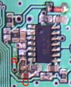
- cut the trace between the southern pin of the LM1815 3pin header and GND nicely. On v3.1 (as on the pic) the most convenient location to cut the horizontal part of the trace, while on v3.2 the most convenient location is to cut the vertical segment of the trace: but the idea is the same. Use a sharp knife, don't hurt any other nearby trace. A capacitor (on the pic, marked "C") will be installed over this tracecut, so scratch the solderprotect at the 2 ends of the tracecut
- and solder (new, from the GenBoard/VerThree/RescueKit) 0805 size
- SMD 100k resistor (on the pic, this is the resistor near "R"). A pad from the LM1815 3pin SMD jumper is reused, and a pad from where C38 was removed from.
- solder C38=220nF capacitor over the tracecut (on the pic near the "C")
Note that a similar solution is the standard factory-populated setup since v3.3 - no modification needed. As a side-effect, this decreases the maximum tolerable noise somewhat, but it's fine with any reasonable quality VR signal and is a big help for those with irregular wheels.
See also