Page about a small addon board with AT2313 microcontroller
- and two LM1815 chips and some other IO circuitry.
The board was originally designed to enable 135-cranktooth InputTrigger support for audi 5cyl engines. This explains the name, but the HW is not restricted to this job.
Note that this board is not needed for that purpose, because of the InputTrigger/AudiTrigger solution.
The PCB
First version of a small addon board (with AT2313 and two LM1815 chips) is being designed to eat signal directly from stock sensors.
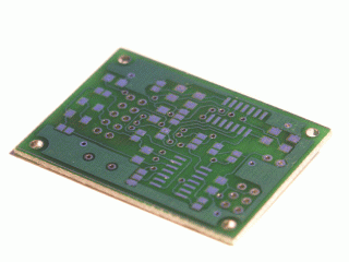
With help from CAM SYNK, it will feed suitable output signal for the mainboard. There are some unused pins available for e.g. frequency input to PWM output conversion or other purposes. Board can be adapted to work with different setups too.
make real circuit from the PCB
The PCB is very nice, but I guess we should order components together.
- let's make a BOM
- 0805 would be better in the future (so GenBoard/VerThree/RescueKit is useful)
BOM:
- C1,C2 22pF 1206
- C3,C4 100n 1206
- C5,C9 --
- C6,C10 --
- C7,C11 --
- C8,C12 --
- C13 10u electrolytic
- C15,C16 -- pwm output
- R1,R5 150K 0805
- R2,R6 5.6K 0805
- R3,R7 1.6M 0805
- R4,R8 18K 0805
- R9,R10 2.2K 0805
- R11,R12 1K 0805 (?)
- R15 -- reset pullup
- R16 -- pwm output
- R17 -- pwm output
- D1,D2,D3,D4 3v9 SOD80C zener
- IC1 AT90S2313S
- IC3,IC4 LM1815M
- Q1 4Mhz X-tal
- JP1 2x3 pin header
- JP2 2x5 pin header