GenBoard/VerThree : electrical connecion of standard HD44780 LCD (like LCD 204B, regardless of color and size)
A Nice drawing can be found on MembersPage/PeterJensenDisplay .
Orientation of JP_LCD pins on GenBoard/VerThree
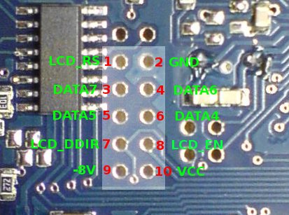
- Note that in the sch the 2*6 LCD connector (don't mix it with the 2*6 ISPI connector: the ISPI is closer to the AVR) is split to 1*2 and 5*2, see image
- never plug in RS232-cable to the LCD-connector, and never plug LCD to an RS232-socket
- Normally, LCD DSUB9 is male on the controller and is (should be!) LABELLED "LCD" (with sticker, permanent marker or other way). If LCD is not in use, stick a tape over the connector.
- while RS232 DSUB9 is female normally via the EC18/harness, or optionally flying loom female or panel mount female on the controller (but in any case, RS232 DSUB9 is female on the controller side)
Data sheet for the 4x20 LCD display sold in the WebShop
- green [Displaytech LCD 204B]
- blue (the slim version that has pins at the sides, not on top/bottom): [CFAH2004K-TMI-JP_Data_Sheet_v1.0.pdf]
- red [datasheet] CFAH2004A-RMI-JP, soon replaced by CFAH2004A-RMI-JT [info]
The DSUB9 old pinout was phased out in favor of the new pinout appr. 2005.May (the WebShop text for the assembled ECM was always authoritive). If in doubt, measure the supply voltage between the relevant pins to be sure. This table will only print well in landscape mode (bad in portrait mode).
| recommended color | JP_LCD | LCD | function | DB9 | DB25 | Note |
| brown | 2 | 1 | Gnd | 5 | 5 | pin2 is not in the leftmost column on the v3 LCD header: Leftmost column is pins -1,0 that are elsewhere in the schematic. Also connect the cable shield to GND signal, but only at the DB9 end (not at the v3.2 board end) |
| red | 10 | 2 | +5V Vcc | 1 | 1 | pin10 is in the right-upper pin on v3 LCD header |
| yellow | 9 | - | -8V | - | 14 | optional: negative from MAX 232 thru R112. Some LCD like slightly negative potential on contrast pin (LCD pin3) for which this can be used. Try the variable resistor method below. If there is no viewability with 0 or positive contrast votlage, or best result is with variable resistor fully set to GND (not a bit of +5V applied), you can try to devise a nagative contrast voltage, starting from -8V instead of +5V for slightly better result. See LCD negative contrast section below |
| - | - | 3 | Contrast | - | - | Solder a 2k2 .. 4k7 .. 10k variable resistor between GND and +5V, with middle terminal to LCD pin3. Set variable resistor for best contrast (it will be near GND). After finding best contrast you can replace variable resistor with matching resistor values. Most LCD like a 470 Ohm .. 1k to GND and 5k6 .. inf towards +5V |
| white | 1 | 4 | RS | 9 | 18 | data or cmd |
| orange | 7 | 5 | R/W | 6 | 15 | data dir. |
| purple | 8 | 6 | Enable | 2 | 2 | latch control |
| green | 6 | 11 | Databit4 | 3 | 3 | |
| grey | 5 | 12 | Databit5 | 7 | 16 | |
| darkblue | 4 | 13 | Databit6 | 4 | 4 | |
| black | 3 | 14 | Databit7 | 8 | 17 | |
| - | 15 | Backlight+ | - | - | You can connect it to VCC with a 22..100 Ohm resistor. Note that voltage drop of backlight LEDs (2 in series?) is sometimes over 4V | |
| - | 16 | Backlight- | - | - | This can be connected to GND via a manual switch. Alternatively it could be switched with a p259 pin, or with a small NPN near the LCD: the NPN base can be controlled through a 1k..2k2 resistor by a free pin of the s259 (allowing software-PWM for backlight dim) |
LCD Contrast
- LCD contrast: there are onboard SMD resistor pads for setting LCD contrast bias, but adjusting this with resistors at the LCD (or heatshrinked inside LCD cable) is recommended: to allow swapping between different makes of LCD
- the "DB9new-pinout" is our standard that we sometimes use for connecting the LCD: eg. male DSUB9 on endplate (or flying loom coming from to ECM), female DSUB9 on cable connected to LCD.
- the LCD has a 2nd connector for mounting convenience, numbered 17 .. 32. It is the very same as 1..16, just add 16 to the pin number. It is enough to connect either one.
LCD that requires a negative (appr. -3V) contrast voltage (very rare among those manufactured after 2012).
The -8V (JP-LCD9, yellow wire according to GenBoard/BuildProcedures/LCDconnect standard colors) for contrast is not needed for most LCD (only a very few green LCD with black frame needed negative, appr -3V contrast). The -8V signal is not available on the DSUB9, so the yellow wire will not be connected in the DSUB9 housing - hotmelt it so it does not contact anything). The DSUB25pin14 has the -8V signal, but, as I said, not needed for the blue LCD.
When bought from WebShop, the crew would warn of LCD that requires negative contrast (this type is not sold these days). Such an LCD will not be viewable at all with -2V .. 0V on contrast.
LCD with -3V contrast
- removed R169 from the board (was 1.0k). (not populated since v3.3)
- after setting best contrast with a variable resistor (alternatively trying 2k7, 5k6, 2k2 and similar values), I applied onboard pulldown to -8V: R112=3.0k
- a good way is to use an onboard R112=2k7 and use 0..510 Ohm series resistor at the LCD, choosing the one from 0, 270 and 510 Ohm that gives best contrast (for that LCD.)
- note that there is no explicite pull to GND (which was R169) or pull to +5V (other than some internal pullup resistor in the LCD): just a pull to -8V resistor of sufficient value
The way it works - for the curious:
The setup for the contrast voltage is effectively a voltage divider from 2..3 resistors:
- LCD apparently has a 4k7 pullup to +5V
- R169, or "R169 substitute on the LCD side" pulls towards GND
- R169 recommended not solder on board, but near/on the LCD from GND (LCD pin1) to contrast (LCD pin3). This makes it possible to have different resistor for another LCD (for exact adjust, without opening the v3 case).
- R112 2.2k .. 3k3, recommended 2.7k (marked 272 or 2701) or 3.3k (marked 332 or 3301), solder on the board pulls towards -8V
The resulting voltage is the weighted average of the voltage "pulls". The weights are the reciprocal of resistor values (1/R), see example below.
Resistor divider example:
4k7 internal pullup inside the LCD towards +5V and onboard R112=3k pull towards -8V the weights are 1/4.7 and 1/3:\n˙1˙
Note that any resistor that is not there (eg. unsoldered) is infinite resistance, so the weight is 1/inf = 0 (no need to calculate with those)
When LCD needs negative contrast, use a DSUB15 or DSUB25, since the DSUB9 does not have enough pins for both negative contrast and busypoll (R/W) signal
The non-recommended way to make negative contrast work with DSUB9 (unfortunately busypoll disabled => not optimal)
- I connected the RW signal to GND on the LCD side (to make place for the negative contrast voltage on the DSUB9 connector)
- configure LCD not to use busypoll. Unfortunately, especially since the firmware got faster, the LCD is often not fast enough and loses sync (mli needed to reinitialize LCD). At low temp, the LCD's internal RC freq gets lower, so the situation gets worse. It's possible to slow down LCD in firmware, but refresh rate would suffer. This is a disadvantage of not using busypoll
- applied JP_LCD pin9 (rightmost pin, under +5V) to DSUB pin7 instead of the RW
- applied DSUB pin7 to LCD contrast pin3
Connecting keyboard through DB25
I propose this pinout that I've used on four boards now, along with the LCD pinout described above:
See also [[Manual: Detailed.Central.Keyboard.Install]]
| JP_PS1 | DB25pinout | Mini DIN6 | Function |
| 1 | 22 | 4 | Vcc |
| 2 | 23 | 3 | Gnd |
| 3 | 24 | 1 | Data |
| 4 | 25 | 5 | Clock |
See also: