Electropneumatic boostcontrol this is only useful for turbocharged engines.
Note! For now this page can be considered a brain storming page, stuff that actually works is found here: BoostControl
Info from here should be moved there or OnlineCourse/BoostControl until this page is deleted.
Why
The maximum boost an engine bears depends on many factors, and it varies across loadsites. To get maximum performance, GenBoard/VerThree implements a fully mappable boost-controller.
Take a look at this powerful system for boost control: http://www.vems.hu/wiki/index.php?page=BoostControllerAdvanced I strongly suggest that we try to implement something like this. -Jörgen
Implementation - mapping
One wants to map desired boost (boost_target) in function of RPM and in function of TPS. For the TPS direction, only monotonous function makes sense (it would be silly to apply lower boost for wider throttle). In the RPM direction the boost_target is often decreased near the maximum RPM.
The following 2-dimensional mapping is used (it will be 3 dimensional when gear-input is actually used, setting BOOSTCONTROL_LINES to 2 or above in my_make):
boost_target = config.boost_targetoffs + b[gear,RPM] * t[TPS]
This provides a simply mappable, yet very flexible controller.
b[] is the b table, t[] is the t table while config.boost_targetoffs is a simple configuration value.
There is a choice in config.boost_conf if
- MAP-target ( bit0=1 note that raw sensor input is used, before calibration-function is applied; this might change one day) or
- boost-target (recommended, bit0=0)
Currently ADC7 is used for the boost input (it's a free, buffered amplifier on v3.2 when only 1 WBO2 channel is used: called nernst2). It will be selectable in the future (any of the 8 MCP3208 channels).
The unit (of configuration values) depends on the pressure sensor input voltage levels:
- b[RPM] = 0xFF means 5V on sensor input (400kPa with a 400kPa sensor)
- t[engine.tps/16] = 0xFF means 1* multiplier, 0x80 means *0.5 multiplier and so on...
Implementation - PID controller
PID controller is used to adjust the actuation command. The PID parameters in config:\nÿ1ÿ
Implementation - Actuation
config.boost_channel is used to select output that controls the solenoid (choose between 15mA .. 350mA .. 15A outputs) , see GenBoard/Manual/DigitalOut .
- Normally a 3 way PWM-capable valve is used: without power on the solenoid the wastegate actuator is fed from the boost pressure; with full power on the solenoid only a small fraction of the boost pressure is fed onto the wastegate actuator: since it is almost open to athmosphere. Continuous transition between these two endstates.
- with a simpler 2 way valve one can try (this is hard!) the following: boost pressure => restriction => electronically controlled valve vents some air to environment, the remaining airpressure opens wastegate actuator
It would be theoretically possible to use an ON / OFF valve that cannot be kept in an intermediate state like a PWM-capable valve: it needs to be switched ON / OFF continuously ( eg. at a slower, 20 Hz) when under control. TODO: We have to add support for this, because many such small solenoids are ON/OFF type.
New experimental boost code
Idea is to keep boost solenoid powered while boost_minpressure < boost < (boost_target - boost_control_threshold). After that point solenoid is driven with variable duty cycle (refDC + calculated correction) to keep pressure in required level.
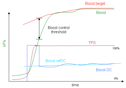
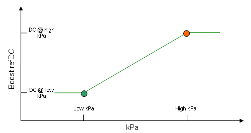
Boost solenoid reference DC% is interpolated from two DC% values at low/high kPa points (both configurable).
It's very easy to tune, just a few parameters to set up. Code has now been tried in two different engines (stock Audi S6 and a tuned RS2) with quite different boost building characteristics and it seems to behave pretty well, although some polishing might still be required.
Open loop boost control
Open loop boost control can be activated from Boost Alternate settings menu. In addition to Open loop-mode selection, choose correct PWM frequency and output channel for boost solenoid.

Duty cycle applied to boost solenoid is read from a boost table according to current RPM:

DC value is used as is, without scaling down by TPS. However if MPC3028 channel is selected from the settings above, DC values may be adjusted by -50..+100% according to value read from ADC.
Closed loop boost control
In closed loop control DC values are read from the boost table according to current MAP and RPM. In the example table below, boost will settle somewhere between 174 and 206kPa lines, since DC will fall rapidly once MAP exceeds 174kPa

Open & closed loop control share the same boost DC table. Open loop uses the bottom line while closed loop may utilize bigger portion of the table
boost control limits for any given hardware
The backpressure in the exhaust will try to open the wastegate, this is prevented by the spring. Thus, a very weak spring can never be used with high exhaust pressure.
Small wastegates with large membranes (large membrane to valve ratio) will often have a larger control range then a large wastegate, which often have the same or only slightly larger membrane size compared to the small wastegate.
A rule of thumb that usually works is that you should have a wastegate spring that give you at least half of your target maximum boost.
Internal wastegates always fall in the 'small wastegate' category. An internal wastegate can sometimes be used up to 3 times it's natural pressure, this is very good for a low power car. But the performance of an internal wastegate is unpredictable, sometimes they won't seal properly and boost will increase slowly. Sometimes they work great until you reach a certain flow, where they won't be able to regulate pressure even if they are wide open. -Jörgen
naive approach - without TPS it would be poor
to have a
- constant boost-target or
- boost-target depend on RPM only
This results in poor drivability. If you want to try it, set t[] table to all FF.
boost-target or MAP-target
Generally we only care about MAP. (more exactly we care about engine torque, but that's hard to measure).
That hints it makes more sense to have MAPtarget rather than boost-target.
However any reasonable MAP-target depends heavily on TPS (while boost-target only depends slightly from TPS), which means
- MAP-target is somewhat harder to map right
- MAP-target is more sensitive to TPS (noise, errors)
- if throttle is released when shifting, this could result in losing some boost (for racecars, this must be prevented with techniques discussed at ALS: detecting shifts and acting upon: not allowing boost to decrease to a large degree)
on the other hand, boost-target
- needs another pressure sensor, to detect boost pressure
- unless boost-target depends heavily on TPS (which brings roughly the same issues as mentioned above, for MAP-target) drivability will depend a lot from throttle: large throttle: bad driveability, small throttle: restricted flow.
What conditions could be used to have best of both worlds?
- when no boost-pressure sensor, boost-target is impossible
- above a certain TPS there is very little difference between MAPtarget and boost-target (surprise: since the throttle is open).
- below a certain TPS MAP-target is problematic (similar problems as with alpha-n), so boost-target is preferrable there
- if switchovering dinamically between boost-target and MAPtarget, the area around the switchover must be mapped carefully, obviously.
From the above, it seems to me that MAPtarget is rather an economy thingy on factory cars. If possible, a boost-sensor is favorable.
mechanical safety BOV
(that vents to environment) is recommended anyway, so if throttle is released very suddenly, the boost won't go sky-high.
Anything below is old, or for developers ... should be organized - split to pages, etc...
Target must be function of (RPM, TPS) was: brainstorming
The better approach is to make boost-target or MAP-target
depend on (RPM, TPS) vector.
Either a
- 2 dimensional table: target(RPM, TPS) (this is harder to map)
- or 2 1-dimensional tables targetmax(RPM) and percentage(TPS) , and multiplication of the 2 results.
- I think the best is to use a targetmax(RPM) and separate percentage(TPS) for low and high RPM (interpolation of course). This means 3* VE_SIZE_RPM entries.
- Since some people have problems to NOT press throttle fully when they need less power, it makes some sense to use another (lower, would this be fully 0-boost??) targetmax(RPM) in (say) 0-1st gear. Note that there is no interpolation between the 2 targetmax(RPM) tables, it's a simple switchover. That means 4* VE_SIZE_RPM entries. This sounds perfect.
other config items:
- input (boost, analog) channel selector: special case FF or 00 (whatever will be off for the input channel selector that will be similar to GenBoard/Manual/DigitalOut) could mean MAPtarget (not separate boost, but using the MAP signal, and algorithm changed accordingly)
- input channel for gearswitch sensor
- output channel (eg. FET) selector
- configuration flags: enabled / disabled, PWM / on-off output, gearswitch input used / not used
- histeresys (could be compile-time)
Eg. there is an RPM dependent P pressure (relative to ambient 1 bar) target active at say TPS > 95%.
And there is a transfer function (of TPS) which determines what the target pressure will be at a given TPS. Eg it can say something like
- 0*P for TPS=0%
- 0.3*P for TPS=60%
- 1*P for TPS=95%
(linear interpolation, more bins, etc...).
Without incrementing the pressure target artificially, with a large throttle there would be very little difference in power between TPS=60% and TPS=95%.
Similarity to idle control
boostcontrol is very similar to idle control
- it can be done with on/off or PWM solenoid
- control a tiny air-valve
depending on gear is a hack without g-sensors - related to TractionControl/Algorithms
Some people have problems (under some circumstances) to NOT press throttle fully when they need less power (eg. in lower gear to prevent loss of traction). This can be helped somewhat with lower boost in lower gears.
Note that a simple solution that depends on gears works well (==near traction limits with fully pressed throttle) only for flat ground. A solution that works for any g (such as a bump) requires g-sensors, and ideally full TractionController with wheelspin sensors. The TractionController should decrease boost (along with other actions) when necessary.
Couple of interesting links to Pneumatic boost control!
http://www.autospeed.com/cms/A_0670/article.html
http://www.autospeed.com/cms/A_0685/article.html
The solenoid activation approach as used by the current Japanese electronics is quite flexible. They either block or bleed the boost line until the pressure is needed to open the wastegate (depending on wastegate type).
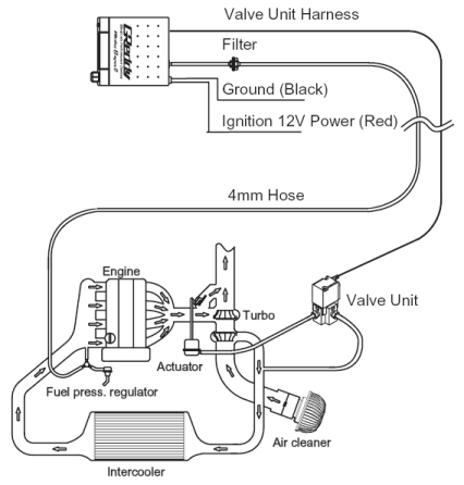
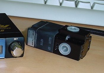
Here's a pic of the valve itself. It's a 3-way with NO, NC, and COM ports. For external wastegastes, the pressure line is connected to the NC port, while integrated wastegates use the NO port. Nothing special about it by the looks of things, just your regular air bypass solenoid.
We need something that can handle at least 4 bar (3 bar + atmospheric) and runs on 12V. 3 way lets us bleed off boost pressure, and works with both internal and external wastegates. I had a quick look on http://www.fas.ch/ and found a Picosol 3 way valve, rated at 6 bar and consuming only 1W. Specs [here]. There is also a options with larger orifices if we are prepared to a) settle for 2 way valve, and/or b) drive higher current solenoids.
My concern with the little Picosol valve is the small flow area. SMC has some 307 valves which are fairly cheap and small, and larger 317 valves with a 12 mm^2 area. Bigger is better here, as it gives a larger flow rate and faster response. Whether it's enough to matter is something else again.
This schematic on the picture is great. I think a new table could be made for boost control. Maybe b-table. It could be RPM, and TPS dependent. We could set the boost target for everey RPM and TPS position(in %). The same method is used in MOTEC electrinocs, and works well in several rally cars in the world.What do you think?
Everything needed for boost controll is already available in the AfreshTiny Lambda meter, meant to be used as Boost control or Wideband Lambda meter.
Is it worth integrating a few things too?
- Turbo timer - fairly easy mod with a relay and 555 timer?
- Boost display - lcd or vfd output maybe? HUD tie in?
- Dual independent valve control - makes plumbing twin turbos nicer, and allows individual tuning for sequential systems.
- Hi/Low boost settings - programmable, with steering wheel or dash mounted switch. TPS controlled even?
- Water injection - ideally with knock detection tie-in.
- Intercooler spray - linked to thermo sensor to trigger when intercooler isn't effective enough.
- Nitrous oxide anti-lag - boost sensing to give a shot when turbo is spooling up, then cut out when full boost is reached.
It's probably good to check out the competition, so here's some current aftermarket offerings:
[Greddy Profec B-Spec II] (MembersPage/RichardBarrington has this one)
And some reviews of some of them:
http://www.sportcompactcarweb.com/tech/0207scc_boostcontrol/
http://johnmonnin.netfirms.com/Boostcontrol.html
A problem I about to face is the frequency of the PWM:
PWM frequency will be dependent on the type of coil in the solenoid.
Norgren do solanoids:
Earlier experiments - from Finland
I have tried out couple of selfmade boost controllers:
- controller1 is basic desing, measure pressure and put it in PID controller
- second version started to regulate pressure before it gets to set point. This one lets pressure out from wastegate if it wants more boost (as recommended in "Implementation - Actuation" above): so if the controller fails it does not lift boost pressure to skyhi.\n
unsigned long RC_Filtter(unsigned long current_value){
 static unsigned long Old_Value;

     if(current_value>Old_Value) Old_Value=Old_Value+((current_value-Old_Value)>>2);

if(current_value<Old_Value) Old_Value=Old_Value-((Old_Value-current_value)>>2);
return Old_Value;
}
we usually use the following: we get extra bits of precision:\nÿ3ÿ
Here is useful tool for example filtering measured boost pressure.
Both of them had same problem: boost was fluctuating +- 5 kPa around target.
Possible reasons
- maybe the solenoid throat was too big ?
- ON/OFF type solenoid instead of PWM-able: even though it has a short closing and opening time about 25ms from off to ON (possible to handle it whit low frequency PWM, appr. 15 Hz) this can account for a few kPa fluctutation
- PID tuning: the PD constants would be particularly interesting. Was the integrator limited?
Any more info and logs ?
So here is an idea: direct mechanical control of wastegate,using RC-servos, or linear positionable actuators. Even though it is possible, it is a good idea to use the pressure (which is there for free) and tiny air-valve(s) for actuation instead of huge, expensive and troublesome servos.
Precision improvement this is commited to CVS head but (since the head is not for production at the moment) must be applied to older revisions manually (patch command).\n
RCS file: /cvsroot/megasquirtavr/firmware/ve.c,v
retrieving revision 1.117
retrieving revision 1.118
diff -r1.117 -r1.118
346c346,347
<   uint16_t rpm_weight, kpa_weight, rpm_weight255, kpa_weight255;
---
>   uint16_t rpm_weight, kpa_weight;    // weight for upper index
>   uint16_t rpm_weight255, kpa_weight255;      // weight for lower index
382,385c383,385
<       w_21 = t_21 * (rpm_weight >> 8);
<       w_22 = t_22 * (rpm_weight255 >> 8);
<       // take care of overflow (price is cycles. >>8 before addition would cost precision):
<       engine.boostmax_target = ( (w_21 >> 4) + (w_22 >> 4) )>>4;
---
>       w_21 = div4096( mult16_8( rpm_weight255, t_21 ) );
>       w_22 = div4096( mult16_8( rpm_weight, t_22 ) );
>       engine.boostmax_target = ( w_21 + w_22 ) >> 4;
if using patch command sounds too complex (it is not) you can just change the #ifdef BOOSTCONTROL .. #endif part in ve.c to:\nÿ5ÿ
Boost-transfer function learning
Many people claim that most boostcontrollers don't work well. It probably means that very few controllers do proper auto-learning. And it's definitely not easy to tune the parameters manually. Also, the importance of the "fixed restriction" sizing is often neglected.
We should implement some autolearning (maybe with PC-assist) to provide a useful system for non-experts who cannot tune properly, and would claim that "ain't work".
It looks somewhat more complex than VE autolearn (which has been implemented for ages).
The convergent behaviour is the simple part. With any PWM-duty, the boost will not raise above a certain value for long. Eg. 0% => 40kPa, 100% => 120kPa (almost linear). The hard part is the transient behavior. Even the transient behaviour model is relatively simple (assuming sufficient precision, of course) but measuring some constant parameters of the model is hard.
A good question is if PID control is good enough or not. PID is good for linear system. PID is suboptimal for systems that involve saturation (nonlinearity). The flying characteristics of the F16 fighter significantly improved when they patched the PID control (with a few lines?) to consider saturation.
- google words: learning transfer function boost controller frequency FFT PID
- http://www.ece.unh.edu/robots/frain/jon_paper.htm
- Jorgen said that everyone (mainly the Japanese) failed to apply fuzzy logic successfully
- frequency domain log-analysis should reveal a lot of truth