Analog input related subpage of AfreshTiny
The analog input can be
- logged with megatune (round_2007-04-25 or newer firmware required)
- scaled with a linear or nonlinear curve, than apply final scaling and offset (inside the device) [download/ round_2008-02-12] or newer firmware required
- display the 0-2024 value on the lower 4 digits (instead of EGT). With the calibration this can be set like 0-120.0 (for MAT Celsius) or 0-05.60 (for 5.60 bar fuel pressure) or 0-081.2 (same fuel pressure but PSI unit). Dot can be placed anywhere, or omitted.
- the same value logged with megatune
Use a 10k resistor to connect a 0..5V signal to the analog input (DSUB15/pin8).
This will add some added protection.
Analog input curve
Nonlinear curve is useful for (NTC based) CLT/MAT/head temperature sensors or resistive fuel pressure sensors, or allows some cheating with linear sensors ;-)
A linear curve is shown (0..240 in steps of 15):
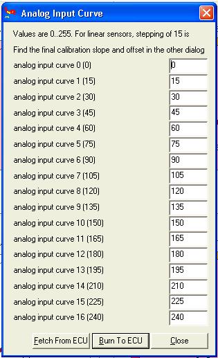
Note that the analog input settings (calibration and offset) are applied AFTER the input curve. The displayed (and logged) value is curve(adc) * cal/32 + offs, that is 255*255/32+255 will display a maximum of 2287.0 (or appr 2032 with offset=0). Dot can be placed anywhere (or omitted), good for convenience only.
For an NTC sensor (with matching pullup if necessary), EasyTherm tables (or the csv spreadsheet file with all sensor data from recent propertherm zip) can be used to fill in the nonlinear points for certain sensor. If you have a certain sensor, or a few points, you can ask for help. You are also welcome to share (and back up) your work here for your sensor and any experience.
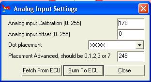
Button threshold can be adjusted (Analog input settings menu, since 2008-02-12), Button_threshold=175 is a good starting value (appr 3.4V). Button_threshold=0 disables the button-switches-displaymode function. If the button has no effect, check this setting.
The measured analog input voltage is effected while the button is kept pushed, this is normal. This can be used to place "index entry" into logs (to make certain parts easier to find when analyzing).
Raw (unprocessed ADC) logging - for experts only
'A' command logs a total of 30 bytes. 14..29 are the 8 internal analog signals in 16bit big endian format
- the analog input ADC (that also has the button at most significant bit) is ADC 4, so 14+2*4=22:
- offset 22 is high byte
- offset 23 is low byte
"Raw reading", 0..255 or rather 0..65535 is useful for calibration.
For linear signal like MAP or TPS a simple 1-line is enough in round.ini
For nonlinear signal, like NTC temperature sensor, fuel pressure with pullup resistor, a megatune calibration file is needed. Provide at least 3 calibration points (more is better) for your sensor (also with button pressed for each point if you care to read the signal while tweaking button).
There is probably little reason to use the unprocessed signal, maybe if one wants a crazy curve with more than 17 points
Using high output impedance transducers with round devices manufactured before 2008-10
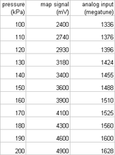
Using the analog input with OE Marelli MAP sensor makes some problem as we discussed on the vems.co.uk forum [1]with Rob. He adviced me to write here my observations.
I used an OE Marelli map sensor ( pdf datasheet is [2] ), measured the applied pressure, MAP sensor output signal and megatune raw value (linear curve, calibration is 255, offsett is 0)
The range of the sensor is 250 mV to 4750 mV from 17 kPa to 216 kPa, with linear out.
On athmospheric pressure it shows 2400 mV.
I got this without serial resistor (the map sensor signal into the vemsgauge analog input):
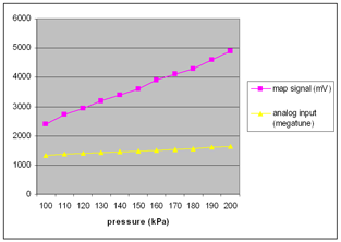
The positive range is nearly linear, but the vacuum is unusable. The sensor can't pull the signal below 2400 mV. Even than it is able to measure below athmospheric pressure, just compensate with the 17 point curve. (without connected signal line the map sensor out is working properly of course).
I made another measurement without the sensor:
- disconnected analog in (4v) megatune shows 1520
- pull the ground (0V) shows 1040
- pull up to 5V shows 1600
Calibrate the 17 point curve so it shows 0 where you like (eg. when connecting ground). That's all.
The input impedance of round devices since 2008-10 have much higher input impedance (around 40 kOhm). Therefore it is easier to use with high output impedance transducers. Recommended operation modes:
- leave analog input pin open (not connecting signal)
- button_threshold=175 (not 128 as the dialog in older megatune round.ini suggests)
- connect signal to analog input through 0..10kOhm resistor
- disable button (button_threshold=0)
- connect signal to analog input through a higher resistance series resistor (around 100k)
- it becomes important to change the 17 point curve for proper calibration
- set suitable button_threshold if it is intended to use the button