Changes by last author:
Added:
|
For ALS operation/config settings, see
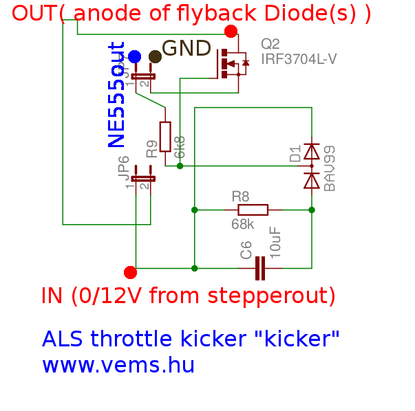
** and/or old MembersPage/GaborRacz/NewAlsLaunchAndOthers page Some installers use trunk-opener "throttle kicker" solenoids (often from VW vans), notably those with 10..30A supply current overheat if operated for longer than a few seconds (say >5 seconds each time, without a similarly long cooling period). Eg an installed solenoid worked for years, with most rally drivers on most rally tracks, * but overheated on a track where the driver drove with ALS throttle kicker solenoid almost continuously powered * a simple PWM-ing circuit solved the problem, that kicks full voltage for appr 150..250 msec than applies PWM-ing for the remaining of the activation. ---- kicker of the throttle kicker solenoid * ALS throttle kicker with powerful N-FET (0.003 Ohm <= Rdson <= 0.009 Ohm) ** external flyback applied to the throttle kicker (eg. 4, or min 3 BY399 in parallel). The common cathode must be connected to the +12V of the solenoid (the common anode to the NFET drain). * Powerful N-FET (eg. IRFB3306PBF N-POWERFET 60V 160A 230W 0,0033R TO-220) ** with heatsink (make sure the cooling is isolated from GND, since the body of the FET is connected to drain, which is switching to >12V ). Plastic screw, "mica" (or other heat-conducting) insulation behind the FET, and black anodized heatsink is best ** the brown GND (NFET source) and red (NFET drain => switched output of solenoid) wires must be beefy (eg. 2*1.23mm2 PTFE insulation wires in parallel). Normal PCB traces would burn if not strengthened. * NFET gate PWM-ed via 12V [NE555 circuit] and 6k8 series resistor (Lezsi, what freq did you set the NE555 to ? 200 Hz ?) * stepper ALS throttle kicker output (stepper output is also 0/12V) and a simple dual diode and RC(=68k*10uF) circuit ** 20uF (2 x 10 uF in parallel) can be used for longer (than 100msec) powerup-kick circuit:
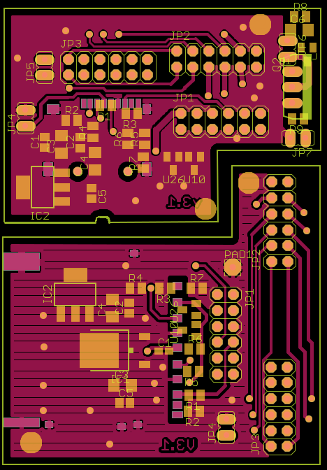
---- Layout example: RC and BAV99 at the top right (otherwise unused part of an internal-SD adapter circuit). Only 4 added components with BAV99 dual diode: can be easily built on small proto PCB. (the 5th component, the TO220 NFET has direct wires, and is bolted to the heatsink anyway)
|