Changes by last author:
Added:
|
EC10
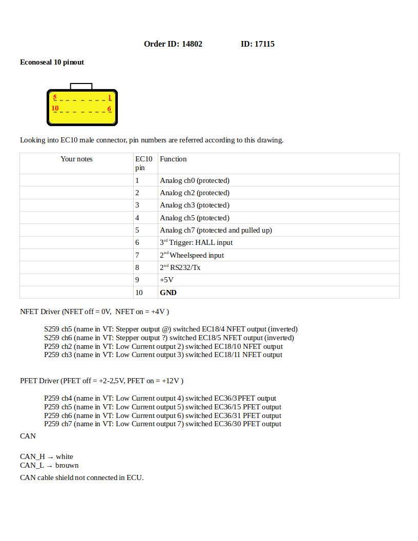
Please scan (or at least photo) the EC10 paper immediately when receiving, and backup reliably (to long-term-redundant-storage). See connector pin numbering for EC10: [typical pinout] Notes: * EC10 male connector pin numbering is mirrored with respect to EC18/EC36 male pin numbering concept, this is historical: although quite unfortunate, (to avoid confusion) kept as used in the relay part documentation originally. Just follow picture, showing corner pins 1,5, 6,10 * Actual EC10 pinout depends on order circumstances (eg. requests in ordercomment, and other factors), so often diverts even in case of same ECU type (eg. VEMS with motronic55 AAN pinout, or "ECU VEMS V3 internal CAN") ---- During verification measurements of v3/17115 "ECU VEMS V3 internal CAN", start from this hint:
* EC10/1 analog input (eg. mc0) * EC10/2 analog input (eg. mc2) * EC10/3 analog input (eg. mc3) * EC10/4 analog input (eg. mc5) * EC10/5 analog input (eg. mc7 ... measure pullup) * EC10/6 3rd trigger (HALL) - useful for activation * EC10/7 2nd wheelspeed * EC10/8 2nd RS232 TX * EC10/9 +5V * EC10/10 GND (measure connectivity to EC36/26 GND, start with this). See bottom of [VemsTune HELP analog inputs page] : * Connect the pin in question through a 2k4 or 1kOhm resistor to GND, than release or connect to +5V ... use DVM and VemsTune simultaneuously, take notes. ---- See also: GenBoard/Manual/EcuEcTen |