Changes by last author:
Added:
|
Fuel-feed related page for MembersPage/MarcellGal/EngineSwap
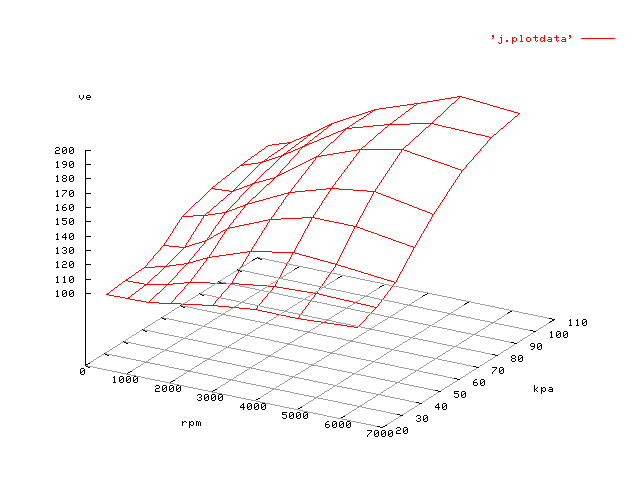
VE table (with intake actuator in highRPM position)
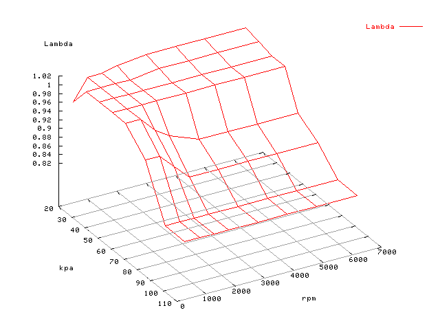
Lambda table:
TODO: * get a 2nd fire extinguisher * my dashboard CLT is not yet connected. If I find connection (wire), it would be nice for lambda. Scale is 84..106 (originally Celsius). Maybe I can do some tricks to make it sufficiently fast. Any info is welcome, I have no idea about it's electrical specs: only that it's cheap GM CLT-gague. The fuel system is complete. DONE: * higher pressure fuel pump installed * FPR installed * plumbing * verify injector resistance with DVM (from the ECM side of the harness). Both banks now measure appr. 6 Ohm (2 injectors, 12 Ohm each) after fixing the broken connection inside the daewoo harness * VE tuned (with lotsof help from WideBand based incredible EGO correction and ve learning) ---- Fuel lines and FPR DONE. * Fuel lines are "standard" (Jorgen's word) 8mm external dia. There are rubber-like tubes clamped to the end, with internal 7 mm dia * the fromtank end of the rail has a tube that should fit * the FPR => line (to tank) fitting is solved, I hope. [see pics] * we found out which of the 2 tubes is the pressure line from the fuel pump (the other is the return line): it was obvious by looking at the lines more carefully, from the tank. ---- Intank Fuel Pump Mounted in the tank untouched. The original engine is 75Hp at 0.76bar, I thought and hoped the same fuel pump is used for engines with 147Hp at 3.0 bar. At least the Etzold book does not talk about different fuelpumps for different engines. Anyway, it turned out that higher pressure fuel pump was needed (80 Euro). I'm kindof biased to measure fuel pressure to be sure. * Maybe the 7bar MPX700A would be sufficient. * Maybe a mechanical round gauge (I have a small round 4 bar unit, but might it be designed for air?) Fuel must not go the the cabin, not even a fuel gauge * people keep saying that oil pressure sender is far the best option to measure fuel pressure - seems right. But installing the oil pressure sender is no way easy. Oil pressure sender has a 10mm external fine-thread (1mm, or even finer?) male thread. I had a hard time to find a simple FPR => tube fitting. Not sure how I could fit this. ---- FPR was missing from the end of the fuel rail on [image 5]. FPR uses a vacuum port on the end of the intake manifold for it's reference... According to H.R.Etzold book (Opel Astra), page 96. drawing D5891, items 11..14 the 0.76bar FPR (swapped out with the old engine) is in the TBI unit on the original engine (simple spring-type). I bought a used (supposedly 3.0 bar) FPR for 14 Euro that seems to fit. The fuel fittings are now done. ---- Injectors * 4 port injectors are mounted, good for appr. 110..120HP. * at the moment arranged in 2 banks (factory). ** DROPPED: find bigger injectors if possible, upto 180Hp (@ 3bar fuel pressure) * LATER: rewire the injectors for sequential. Currently arranged into 2 banks with a 3-pin connector. * LATER: change the fuel filter (Aeromotive do a nice [10 micron] filter) * LATER: water injection would be nice for ignition advance (=>power) even for NA: not worth to spend much though... Is there a poor-man's water injection ? I have windscreen washer pump and can flatten tube to make a mist. Headlight washer pump might be needed (for higher pressure => better mist) ---- Injector wiring notes * the right pin of the 3-pin connector (when looking into the inj harness, while tab points up) goes to all 4 injectors (the closer pin), good * the left pin goes to injector 1 and 4 (far-pin) * the middle pin goes to injector 2 and 3 (near-pin) I had to fix injector harness, and several other wires in the daewoo harness. Unfortunately a bit short of harness wires, mainly because of the WBO2. Problem is to get the rubber at the firewall seal properly after adding wires. But I had to add some shielded cables and a few 1mm2 wires for clean GND signals. ---- Injector opening config - GenBoard/Manual/Config/InjectorOpening The injector opening parameters includes the injector closing effects. Basically "opening - closing" time. Note that closing depends on flyback HW as well. * used low voltage 0.7V + 0.7V flyback, as on GenBoard/Manual/DDFlyback * kpafac=34 (decimal 52) for 104 kPa MAP sensor * kpaofs=0 (not sure about this, MAP sensor not calibrated at low MAP, only at athmospheric 101 kPa) * injopen=20 # 32*16 usec = 512 usec (a bit too high, see notes below) * battfac=10 # +- 16 * 16usec depending on VBATT * injocfuel=10 # max rampup time at VBATT=7V is 16 * 24 usec * injrampup_battfac=FF # min rampup time is injocfuel*77% If you examine my tuned VE table (MembersPage/MarcellGal/EngineSwap), you will notice that lowkPa values are smaller than highkPa values. eg.: * 0x75 at 30kPa,3000RPM * 0xAF at 90kPa,3000RPM This has nothing to do with the VE being so different. In fact the difference comes from 2 effects: * the above injector opening parameters are a bit too high (because of injector closing effects), so they add more pulsewidth than necessary: the MAP dependent component therefore becomes lower, which shows up in lower VE values at low MAP * MAP measurement offset: MAP is calibrated at 101 kPa only, and not calibrated at 25kPa. In this case this is a very small error, but would be significant for a badly calibrated 400 kPa MAP sensor. Config * alternate=11 (01 for 2 injector banks; 0x10 added for squirting both banks simultaneously at cranking) * divider=02 * req fuel=50 (80 * 100 usec = 8 ms), note that VE values are way above 100 for higher resolution * lambda table - pie to make a good lambda for NA. With more monitoring it could be slightly leaned at some places * VE (j) table learnt from WBO2, smoothed a bit, so loadsites not visited during the learning session are nice as well. Now ve_learning is disabled in production, but WBO2 is still full-time on for incredible EGO correction and monitoring * injpwmt=FF (no pwming) h[0]=10 04 01 08 02 20 40 80 Fuel pump relay is driven from: * fuelpump_channel=INJFET_7 (7th element of h[0] => mask of 80) I decreased ego_pid_kp (which is "incredible speed limit") so I can decrease ego_lag * ego_lag=05 * ego_pid_kp=40 The old ego_lag of 21 engine cycles was way slower than justified for the very fast and precise WBO2. Although seat of pants (and EGO correction on display) shows it's very nice, some detailed analysis wouldn't hurt to fine-tune these on scientific base. ---- Old: hunt for FPR output fitting Finally I found a piece to mate the 7mm internal dia rubber tube to the FPR output: (an inverted cone female swivel). After spending a day with the hunt, it was very close to my place, and very cheap. [FPR] has male 14x1.5mm output thread, with a reversed cone (24 degree??) inside. * Aeroquip part number for an adapter from the OEM fuel rail connection to an JIC (AN #) fitting but I (==mk1_G, thanx, BTW) couldn't find the parts number in their catalogue. Aeroquip Item: 15-163-6-6 (TIN: M0040247). * On [thinkauto] HETAF2-55-6 for £11.85 is a "Straight female fitting" but maybe I need a bisexual one * google words: M14x1.5 female * [http://www.jgbhose.com/base_pages/coupling/GS.asp?id=1&sType=SAE%20100R15&tName=GS%20Stems%20and%20Ferrules%20(except%20-24) jgbhose] something like GS-FBSPORX or GS-FKX - nope, they are too big * [instructions of a tube crimping tool] - it says 38 Nm torque must be applied (for 14x1.5mm size cone fitting) for good sealing. ---- See also |
![[image 5]](http://www.american.hu/GenBoardv31/engine/Daewoo/DaewooEngine1.6L16V_intake_output_05.jpg)
![[FPR]](http://cell.dyndns.ws/efi/engine/Daewoo/smallparts/FPR/FPR01.jpg)