Changes by last author:
Changed:
|
This is a 3-pin solenoid. I did some measurements to it:
Resistance between pins: (1) - 20ohms - (2) - 20ohms - (3) (So there are 40 ohms between pin 1 and 3) Without connection there's no "default" position. |
| This is a 3-pin solenoid. Guess it is stock on motronic 1.3 systems for M20 engine. |
| Measurement |
| Finally I've made measurements to motronic control signals. All measurements done with ignition on but engine is off. |
| Measurements I made on it: MembersPage/GergelyLezsak/IdleControl/Measure |
|
I've been seeking long for specs. about notebook's mic. input. I found this:
|
| Docs found about similar valve: MembersPage/GergelyLezsak/IdleControl/Docs |
| As you might found out I used the (mono!) mic input as a scope. |
| Pictures I made: MembersPage/GergelyLezsak/IdleControl/Pictures |
|
Here are the results:
|
| Driver selection: MembersPage/GergelyLezsak/IdleControl/Driver |
| First pic is channel 1 (solenoid pin1), second is channel 2(solenoid pin3). It's quite obvious that the sum of the duty of the two channels is appr 100%. |
| Firmware related: MembersPage/GergelyLezsak/IdleControl/Firmware |
|
Third image is when both channels connected. How? I used to connect the ground of the notebook and the car, and the signal was connected through 2.1k resistor for one channel and through 10k resistor for the other. (I'm not sure which one is which)
* Yellow is the measurement * red is what I guesstimated for the real signal. (Since measured through a series capacitor). Apparently you (for some reason) assume that the notebook input inverts the signal. On the third picture I tried to put them together but not sure that it's the good alignment, unfortunately 10kOhm channel is not so different from the case when both channels is "on" (switched GND). These are my voltage calculations for all of the cases: |
|
----
Actually we've got a hacked firmware to control it. Now the valve is moving smoothly but still has some instability in idle. It might be related to mechanical problems instead of configuration/control. (Not sure) |
|
R2.1k R10k Voltage
off off 2.28V off on 1.82V on off 1.02V on on 0.92V |
| ---- |
| Frequency is about 100Hz for sure. |
|
I made a measurement to the current GenBoard control too:
It was only the first channel I checked, because it was way too fast to see difference when both were connected. (And not too interesting at all, we know how it's working :) Appr. ~2kHz! Actually it is soft-PWM controlled, which means DC is controlled with high resolution (at high freq); also with small overhead. |
| Configuration and other issues |
| * I've modified the firmware to call the idle solenoid code with 100Hz frequency (20 times slower, than original solenoid freq in GenBoard). It seems to be working now, changes like 1-2 (hex) iac values reflected quickly in rpm. However PID config changes doesn't really alter the rude fluctuation of my idle. It changes in a ~160rpm range without characteristic period. [Here] is a datalog XLS from megatune, I've created a diagram into it also. Note that with fixed iac value the engine's idle is altering appr. the same way. (Maybe compression diff. between cylinders? I've a somewhat modified camshaft maybe with +30 degrees opening.) |
| PID config changes doesn't really alter the rude fluctuation of my idle. It changes in a ~160rpm range without characteristic period. [Here] is a datalog XLS from megatune, I've created a diagram into it also. Note that with fixed iac value the engine's idle is altering appr. the same way. (Maybe compression diff. between cylinders? I've a somewhat modified camshaft maybe with +30 degrees opening.) |
| * Different alignment of the two signals matter none, that's almost certain. |
|
** Marcell played around with PID settings, without success. P setting of 66(hex) and up became divergent so we choosed 33 as a stable value.
* Different alignment of the two signals shouldn't matter, that's almost certain. |
| - mixture is too lean, specially at lower map values (idle 'hunts' between two or more VE table bins -What amount of VE difference should cause this change?). -I'm targetting lambda 0.8 around idle this time. However, (as you might see) I've quite high (54-60kPa) map values to get idle. So it seems (std. value is around 35-50 kPa), camshaft duration and overlap definitely bigger than in std cam. |
|
* mixture is too lean, specially at lower map values (idle 'hunts' between two or more VE table bins
** smoothed VE and lambda table in the idle area, no change. (I'm going 0.96 lambda this time) *I've quite high (54-60kPa) map values to get idle. So it seems (std. value is around 35-50 kPa), camshaft duration and overlap definitely bigger than in std cam. |
| - air leaks inlet manifold, throttle body flanges, in hoses etc. -I'm not sure how to check this. Several methods by listening ie. measuring with acoustic leak detector or spraying 'start pilot' gas near at suspectible leaks - are the most easier ones. |
| *air leaks inlet manifold, throttle body flanges, in hoses etc. **Tried to spray suspicious areas with starter spray, no reaction. |
|
- manifold pressure that MAP sensor 'sees' is fluctuative ie. not 'constant'. Add a 'little can' (fex. moped fuel filter) to hose between sensor (should install it to hose quite near the MAP sensor) and manifold plenum connector. -Map sensor is a bit far from the engine (guess ~1.5m pipe length) is it a possible cause of fluctuation, or what? -My analog boost gauge has at least similar length pipe, but I don't see it's fluctuating. However, that's not so accurate.
1.5 meter length hose should not cause any problems if it's inside diameter is reasonably small fex. around 2-5 mm, and instrumentation is done properly ie. absolute pressure that sensor 'sees' is constant etc. as per. above. |
|
*manifold pressure that MAP sensor 'sees' is fluctuative ie. not 'constant'. Add a 'little can' (fex. moped fuel filter) to hose between sensor (should install it to hose quite near the MAP sensor) and manifold plenum connector.
**Map sensor pipe has 1.5m length, but that should not cause any problems if it's inside diameter is reasonably small fex. around 2-5 mm, and instrumentation is done properly ie. absolute pressure that sensor 'sees' is constant etc. as per. above. |
| - Std. M20B25 camshaft timing has relative short duration (around 220 deg). Increasing duration increases overlap (more if lobe centre angle is lesser), which has ill effect on idle stability but, 250 deg. cam should work. Altought - might want to check cam timing. Cam degrees after top dead centre when inlet valve is fully open ? -How to measure that? |
| * Std. M20B25 camshaft timing has relative short duration (around 220 deg). Increasing duration increases overlap (more if lobe centre angle is lesser), which has ill effect on idle stability but, 250 deg. cam should work. Altought - might want to check cam timing. Cam degrees after top dead centre when inlet valve is fully open ? -How to measure that? |
| **How will I know the engine is at TDC, and the valve is open/closed? |
| *How much degrees do you advice? (where?) |
|
What do you think?
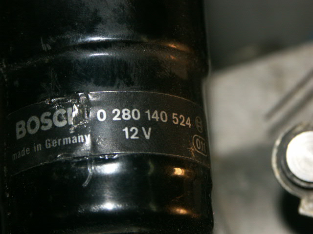
Definitely relative heavy actuator can't cope with such a high PWMming (2kHz), decreasing control frequency was reasonable. MembersPage/BengtR measured frequency from couple of 'similar' (but different part ie. Bosch part number vice) valves, they all were controlled with 50 to 150 hz signals. ---- Control it PWM switched ground to pin1 and pin3 moves the valve to opposite directions, if pin2 has stable 12V+ supply. Connecting pin1 to GND closes the valve. Changed the end of idle_solenoid() in iac.c so it sets 2 output channels instead of one: <code> cli(); digitalout(config.iac_sol_channel, output); sei_nop_cli(); digitalout(config.iac_sol_channel + 0x10, output ^ 0x80 ); sei(); </code> config.iac_sol_channel has been set to 0x36 (stepper channel A) This way 0x46 (stepper channel B) is inverted. Connections are according to GenBoard/Manual/DigitalOut/Table. IAC control seems working now, I can use mdh/mdi commands and idle changes. For warm engine value around mdi70 seems a good approximation for 900 rpm. I've found that small changes to value doesn't reflect in rpm immediately (or at all). Big changes (like mdiff :) are noticeable promptly. Idle controlled by GenBoard, but the idle controller (reference positions, ign-adv based control, iac-PID) is not yet tuned. Kindof instable now, see logs: * [ Config and data saved in MegaSquirt] * [Datalog (XLS) from megasquirt. I've made a chart in it also] Definitely decrease P and D (start by cutting to half) and play with I-term as well. After PID is tuned, to get faster behaviour the proposal on bottom of GenBoard/UnderDevelopment/FirmWare/PowerRelated could be implemented. I've changed P and D (to half and even to quarter) values, played with I without success. I can't say there was no change to idle behavior but I couldn't decide which was better since all setting was way too poor. I sticked to use fixed values from keyboard but even this cause big (5-800 rpm) changes in idle, sometimes idle get lost between gear switching and engine halts. Maybe we've to look after some different way of controlling, or even spy after motronic's controlling mechanism. One for sure, motronic actuated the valve with a much lower (~50 Hz by ear) frequency than we do now. ---- Driver selection 14V/20Ohms = 0.7A capability with flyback If the two coils have independent magnetic paths (which I expect), low voltage flyback is the best. Either: * 2 free FET (TO220 or DPAK) with flyback. The injector FETs have flyback applied already: on this 6 cyl machine that would use the two remaining high power FETs if you use the injector drivers, none to spare for other functions. * or 2 stepper channels (free anyway, seems like a good choice) * or IGBTs. the IGBT-s have internal 400V clamping, but IMHO it's a bit rude to dump the coil energy in the IGBT. So I recommend to apply flyback diodes onboard if you choose this. (there are throughole pads for one end of the flyback diode at the IGBT) If the 2 solenoids have the same magnetic path (very unlikely, only unipolar steppers have that), than high-voltage flyback (16V or above, 18..20V recommended) needed instead of low-voltage flyback: * FET is good, but with high voltage flyback. Throughole 18V transient suppression diodes are easy to mount for either the DPAK FETs or a free TO220 FET. ** if using the injector FETs with already applied low-voltage flyback, an SMB diode must be replaced with an SMB transient protection to get high-voltage flyback * SN754410 stepper chip is not sufficient, it has internal low-voltage flyback. L293 would work with external diodes, but we don't use it since v2 * IGBT is good, but high voltage flyback recommended. ---- Docs found Found some info in haltech docs: BAC Hi BAC high is a form of BAC idle control that is used for 3-wire BAC valves with two coils. These valves are sprung so that when no coils are energised, the BAC valve sits at 50% open. Two PWM signals are used to move the coils. One signal moves the valve from 0% to 50% open, while the other signal moves the valve from 50% to 100% open. The BAC Hi output moves the valve from 50% to 100%. When the target position for the valve is between 50% and 100%, this output will provide a signal from 0% to 100% duty. Sounds relatively simple. Some changes and things to-check required in idle_solenoid() : * 2 channels must be used instead of config.iac_sol_channel. However, I don't see a reason to add a config variable to make them independent. Eg. config.iac_sol_channel and config.iac_sol_channel+16 would work well (that means if mdh02/mdh82 is used for one solenoid, mdh12/mdh92 can be used for the other). * if one solenoid is powered, the other must be unpowered. This can be remembered or done dumbly every time (SRAM/cycles tradeoff). * iac_conf can be cleaned-up (while merging the unipolar-iac support) as on GenBoard/UnderDevelopment/FirmWare/PowerRelated to make space for the new bit that activates BAC-mode. All idle control tuning and setup is done with the BAC Hi output. Refer to section 3.13 for details on how to tune your idle control. BAC Low The BAC low output is used to control the BAC valve when the target opening is 0% to 50% open. When the valve target position is 0%, the output duty is 100%. When the target is 50% open, the output duty is zero to allow the spring to return the valve to its default position. BAC Inverted For 3-wire BAC valves that do not have a spring to return the valve to the centre position, use BAC and BAC Inverted to control the valve. Connect the BAC output to the coil that pulls the BAC valve open. Connect the BAC Inverted output to the coil that pulls the BAC valve closed. The BAC Inverted signal is a complementary signal to the BAC signal. If the BAC output is set to 70% duty, then the BAC Inverted signal is set to 30% duty. All idle control tuning and setup is done with the BAC output. pwm freq maybe in 200-1000hz range? ---- NOTE ! "Original" wiring ('0 280 140 509' valve (from E30 -89) is as follows... Pin 2 -> 12V supply. pin 1 -> to Motronic ECU pin 22 (white-green) Pin 3 -> to Motronic ECU pin 4 (white-yellow) wiring might be same with the '524' valve ? * Thanks Ben, I'm not sure where it came from, I think these are very similar ones. With motronic control it has some "Brrrrr" sound like the 50Hz on a transformator. ---- Picture of stock(?) idle air solenoid:
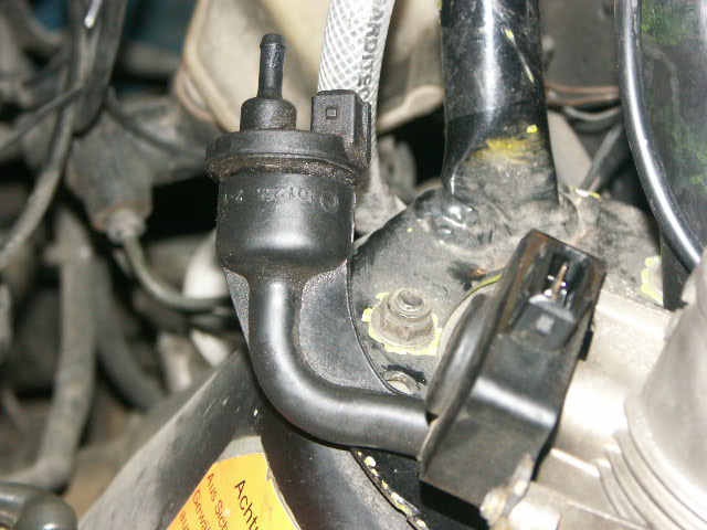
---- System had an EVAP purge canister valve (said 'auxiliary air control' earlier) also:
I'm not sure whether this is part of current motronic config or it comes from some jetronic system. Harness was connected however. |
|
options
* leave it out and block its connection from throttle body. * or you can control it from GenBoard. A purge canister can trap significant amount of gases (useful in the engine, unwanted in the athmosphere unburnt) escaped from the tank on a hot summer day (such as today). ** resistance is 46 ohms. This might be a useful idea, but has low priority at the moment :) ** actually I used the drill in throttle body for [IAT] |
![[IAT]](http://quasar.dynaweb.hu/~lezsi/bmw/conversion/iat.jpg)