Changes by last author:
Deleted:
|
Hopefully I got a bench setup both for the Weber OEM injection IAW ECU and for the Vems.
'most recent post is at the bottom' ---- '''1st tests fw 1.2.12' GOOD NEWS On the next figure, the strobes regarding one cylinder are counting from the last: - Ignition, - Vems Injection, - IAW Injection
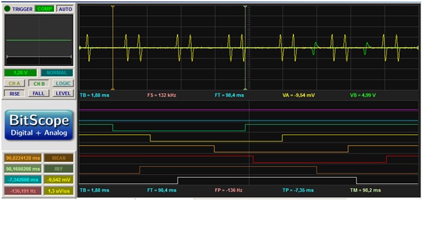
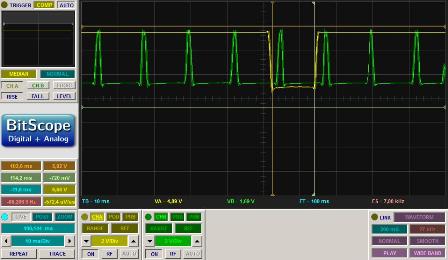
The settings for the injector are the one computed by VT from the engine specs and as we see not too far from IAW Injection outputs * 1.2.13 (or newer: and new VemsTune ) ** for odd-fire maserati, injection is 30 crankdeg delayed every 2nd injevent (1,3,5) ** We BENCHTESTed 1.2.13 (https://cell.dyndns.ws/f/ May 13). ** inj is also oddfire 90,150,90,150,90,150 see logicdata in http://www.vems.hu/files/maserati/ *** (fphil)what was the injector delay set for this run? *** the config (extracted from vemslog) you sent via email * Adjust the injector delay (in function of RPM) if necessary, to get desired positions. Let us know if you find it's preferred to delay inj 0,2,4 instead (so that adjusted injangle is real as adjusted without cheating) * Older fw (was evenly-spaced injection events): tested the Vems injection outputs using the sequential injection settings of the config file (fw v1.2.13 from 2013 April) given by the OddFireSixCyl page. Here below are the 6 Vems output together with the trigs Evenly-spaced. Remember this odd fire engine has an ignition pattern as 90, 150, 90, 150 , ... and one can expect to have this pattern duplicated for the injection one. ---- (June 2013) 2nd bench testing with fw 1.2.14 As wikied above, the vems support did a May 2nd version of fw 1.2.13 which as been tested good for odd firing at the VEms facilities. On my side I bench tested good fw 1.2.14. Hereafter the results. Settings: Injection timing = 1ms, fuel cut = 7200 TEST I Settings: 1000 rpm EndInjectionPhase = 370°=360° + 10° (crang trig is 10° before DTC)
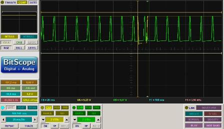
-> the yellow cursor marks cyl 2 which is firing, next firing is done by cyl 5 on next trig 90° afterwhile. The white cursor marks where the injection pulse should have occurs with EndInjectionPhase = 370° -> injection is odd-pulsing alright .Test II Settings: 1000 rpm EndInjectionPhase = 250° = 370°-120°,
-> The white cursor marks where the injection pulseat 370° before cyl 2 TDC -> PLEASE DELAY THE OTHER GROUP OF 3 INJECTORS (say nj 0,2,4 ) INSTEAD * the "other group of 3 injectors are delayed" in [1.2.14] from June .Test III Settings: 3000 rpm, 6000 rpm, 7000 rpm fuel cut = 7200 ... Good similar TestII .Test IV Settings: 7250 rpm ... good, no injection = fuel cut done. . Test V Settings: 7000rpm injection time = 100ms,
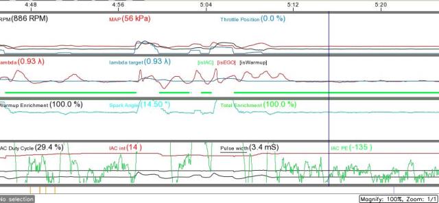
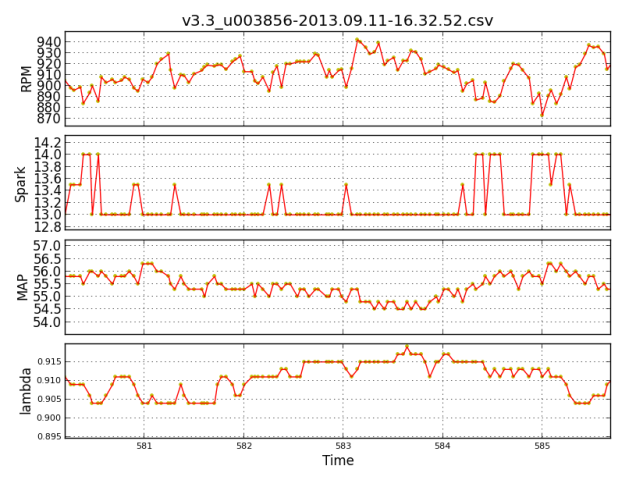
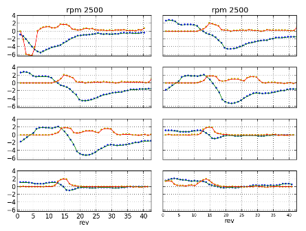
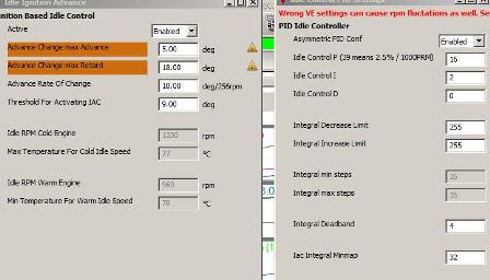
time read on scope = 98,165ms = good. Thanks for the work done to update the firmware Nest step to cable and test on the car ... (I am really slow !!) ---- (July 2013) Wiring the injection Not much work here. I had a spare of an OEM Weber IAW injection ecu, and hopefully, despite the oem injection was semi-sequential every injector was wired down the IAW connector where the shunts were made. I modified the connector and the spare IAW. This one becomes more or less a connector box for Vems, but also running on its own, feeding the fuel pump, getting the MAT and CLT values to be sent to Vems (I have modified the resistor bridge on the genboard). So now, simply by swapping boxes, I can run Weber injection or Vems injection. ---- (August 2013 _1) Running VEMS injection - stage 1- From the IAW eprom I had some idea about the injection map which could parametrised fw 1.2.15 , so first try = first start but several issues: Issue 1: The lambda values are jumping up and down with no reasons By chance G. Lezsak few days before had noticed that this problem was due to a fw bug and the 2013.08.08 built of fw 1.2.15 solved the case. -> Close Issue 2: the lambda values from bank A and B are 8-10% apart, Round values being higher than Vems' On bank B, I had kept Vems Round since I did not have the components to properly wire the genboard for the 2nd wbo2. I had changed the Round factory values(Nernst target) in order to get 20.9 in open air, although I knew that Round takes the reference resistance set at factory along with the sensor to compute the lambda values and so does need calibration a) I went back to the bench. Injectors of one banks have to opened after a delay of 30°, hence a bug could have come from here with the change included in 1.2.14 and 1.2.15. I checked this is not the case. However I noticed a noise say about 2-3 % on the pulse width, with a DC being,per ex. 18.7, 19.3, 18.7, 18.4, 18.3, 18.1% etc, This is not due to the trigger signals which comes from the VT because the periodicity of the pulses is rock solid. It may come from the the computation of the angle derivative, possibly on a too straight way. I saw that RPM is as well noisy on bench without reason. b) Back to the car, swap the wbo2 connectors, round and vems calibration -> round still higher. Finally I put back the original Nernst target value, Round does not gives 20.9 (18.8) but around 1 the 2 lambdas are quite the same!! Probably some kind of non linear correction for large lambda values are not done with Round as it is done with Vems. Better to have known that before. -> Close * "Safe mode" I get to the above conclusion through a big fight with the "safe mode" function and the [help page] explanation. This took a couple of hours (there is no internet where the car is parked). I should have enable an "IButton" at some time and I now had no ign. or inj. (test mode good). To get rid of this "nice safety feature", I finally wrote the "prohibit" word with (190,239). Thereafter the red safe mode indicator went off but still no inj or ign, until, by chance, I upload a fw + config on the genboard which was actually running and fed by the trigger pulse (from another computer), and I miraculously recovered inj + ign. * yes "VemsTune sets correct value automatically after upload of full (.vemscfg) config (to leave "safe-mode"). ** maybe you can recommend a place elsewhere in the help, where one looks first and it's more intuitive to find ? ***the matter is not were the help page is, but rather what it is written vs my genboard disfunction 2computers+2 scopes+myself were working together quite hard but may be toolate at night ;) But for now on to get ign. + inj on that genboard, I do have to fed it with the triggers signals before switch on. * no, with uploaded config (correct config values burnt, that disable safe-mode) can be powered down/up and fed trigger signals afterwards. (it's more usual to start cranking after ignition power is on; of course it'll also sync on a higher RPM signal) ** yes I know, probably there is something wrong with my genboard:I got inj+ign only if I power on after trigger signal is fed. Issue 3: genboard disconnects more than often I thought it was because of the noise of my new injection, or fw version etc .. since before, the connection was steady good. Afters many tests I recalled I changed recently the motherboard of my netbook and I noticed that the prolific cable was shielded on the side of the computer not on the RS32 connector side. I soldered a wire from this usb metallic shield to the car ground, et voilà rock steady connection with prolific. Probably the usb port of the new board is more sensible to the noise that the one before Very good hint, thanks. -> Close Issue 4: Idle IAC I rapidly got reasonable VE and pulse width injection values for lambda 93 at 20° CLT or 90° CLT which compare with the values I had scoped from the oem Weber ecu. However when the IAC DC for weber was about 30% @ 90°, it needs to be 80% with Vems. This is something I do not understand since I have checked on bench the similitude of the Weber and Vems signals (frequency, polarity, ...) * Maybe the weber has a low-voltage flyback for IAC output ? ** low-voltage flyback is not the standard for v3 because 30V flyback gives better injector-control; but also possible to order v3 with low-voltage flyback on 1 or more injector-outputs. ** if using a diode (any diode >=1A eg. 1n4004, 1n4007 or BY399) in parallel with the IAC; anode on controlled IAC pin; cathode on +12V IAC pin. ** but 30% .. 80% is a bit too much to be caused by the switchoff-effect (flyback voltage) ** Just in case... Does IAC regulate in the right direction, btw ? Higher PWM duty % => opens the IAC and feeds more air ? *** yes many possibilities, I would scope the IAC signl on the car, btw I use an ignition output -> Open Issue 5: Idle control PID vs Achille's heel I did no succeed to set the idle as good as it is with oem ecu (cpu 6804) After some tests, I have finally put PID=0,0,0 and set the IAC DC curve as good as I can. So the engine idles as it likes about 950-1200rpm depending on the warm up enrichment curve and VE Before I gave a look to the PID. - First surprise at the right of the set point there is a moving IAC RPM Target (for the P, I and D). Would the Paris'arrow reach Achille heel in a finite time? * yes, if the PID tune is anywhere close, target will converge to final_target RPM (from above!) rather quickly (RPM dropping below is much more annoying than to temporarily have a slightly higher RPM). ** probably thanks to the I action. ** does the I term takes the error from that moving "Final_target RPM". Ah the good old days of analog computing when digital derivatives were not easily at hand! Theoretically this non linear control gives a 1rst order response(exponential), but in practice there is always a significant final error which can only be reduced by a huge value of P which in turn makes the control on the left side of the target instable. So to recover the stability there ones put a large value for D which, because of the noise on the velocity etc, makes a wrong action. - Another surprise, there is no interpolation for the IAC DC between the end of cranking (say 450) and the MAP entry at the first column (say @800rmp) of the VE table. The P term does the job for IAC DC. Hence one may get IACDC=100% with the VE value for 800rpm. Probably when the start is well tune, the engines rpm jump across that gap [450rpm,800rpm] easily and the tuning in this band does not matter. - I have not understood what the option "Asymmetric PID conf" does. * if enabled, bigger (twice) values to feed more air (push RPM up) than to remove air ** what air?, is it the DC value computed by the PID which is x2 when the error is >0 (rpm left to idle set point) and x1 when the error is <0 (rpm right to idle set point or Final_Target_RPM)? - Hopefully the I action is well described. I did not use it yet. Certainly this is the way to go along with the idle ign control. -> open For the present time I need to continue tuning for the steady states, particularly above 1.4 bar. Also I have to set the MAT/TPS enrichment map since actually when MAT=40° idle goes with lambda 0.93, and, when MAT=60°, lambda 1.02. ---- (August 2013 _2)Issue with 1.2.15 built2013-08-28 a. After updating from fw 1.2.15 built 12/08/2013 with the built 2013-08-28, I got: - serious misfires at about 3000 RPM (dwell 2.37ms) - with dwell 2.99ms misfires occur at about 2000 RPM. - With dwell 2.12ms, misfires was at about 4000 RPM. b. Hence I thought one of the coils could be bad. Hopefully I tested again on bench fw 1.2.15 29/08/2013 by increasing RPM speed: - RPM on Gauge happens to be late by 20RPM w/r the RPM set on the trigger tool. c. Finally I reload 12/08/2013: - no more misfire. d. This may come from the change done on fw for coil type triggers which could induced ign. outphasing. On bench, a speed step response shows some difference on the triggerlogs +sparks between the two builts. The 29/08/2013 built being much more reactive I think. e. The vemslog, here joined, was done car stopped. The lambda log shows quite well the default. http://www.vems.hu/files/maserati/v3.3_u003856-2013.09.09-12.08.41.vemslog Beside, the record shows among other things (many of the injection functions are not yet tuned) - a not too bad idle got w/o PID, but with a crazy IACDuty (more about that later on) - a still noisy RPM : per ex. @ 28.123s - 2143RPM, @ 28.170s - 2132RPM, this is an old concern, which, I know, does not matter so much because the inertia of the engine smoothen this high freq noise, but I do not like that. ---- (September 2013 _1) I feel stupid with the DC of the IAC - stage 1- a)As said, I have tuned the VE table to idle about 900 warm or 1200-1300 hot. I tried to used the IAC PID to improve the stability of the idling. I got the following for PID=(40,2,20)
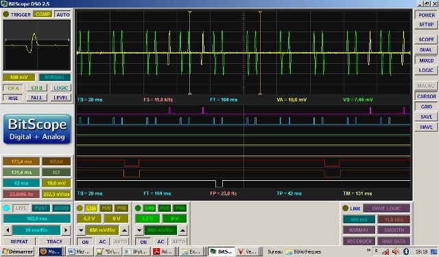
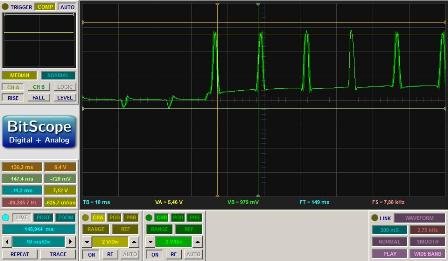
On the left of the picture before the throttle stroke, PID=(40,2,20), on the right side P=0. I appears that the P term is probably of no help. Could be the noise on RPM orbecause the IAC works near saturation. So I turned back to that issue: why the Weber IAW oem ecu idles (warm) at 30% IACDC but Vems does so at 80%, the inj PW=3-4ms (warm) similar to the PW IAW value. I thought this is a case which cannot challenge a scope through tests on bench and on the car. b)On bench The IAC is the well known Marelli Magnetti (ex Weber) VAE V6, 2 lines,PW modulated, with a transient voltage suppressor diode (12V side) integrated. It is used on Lancia, Guzzi etc. 7.5 Ohm impedance. The IAW ecu energizes the IAC by grounding the input port to which it is connected. I rerouted the line to the IgnOutput4EC36Pin11. I tried to set the PW freq at 78.4Hz same as the IAW. I said I tried because the fw use to change the value to the nearest possible c)On bench. The IAC is a 2.2kOhm resistance As noted before, Vems undervalues the DC by about 15%. I got for (VT%, Measure%)=(36.5,44)(43.1,51.1)(57,68.7) etc.. To compare the IAW idle strategy versus the Vems running my first idle settings (no control), I did extensive measurements ||MAP=100kPa || CLT=17°|||||||| ||MAP=100kPa||CLT=91°|||||||| ||RPM||VAE||IAC||Inj16||Inj1|| ||RPM||VAE||IAC||Inj16||Inj1|| ||295||11.3||11.6||9.2||12.6|| ||295||11.2||7.6||8.2||6.6|| ||486||11.4||11.6||9.2||12.5|| ||486||11.2||7.2.6||8||6.6|| ||600||11.2||12.8||9.2||11.2|| ||600||6.4||8.4||8.2||7|| ||800||11.2||12.6||9.2||11.2|| ||800||3.2||7.8||8.2||7.1|| ||920||3.8||12.5||9.1||11.2|| ||920||3.2||7.8||8||7.6|| ||1200||3.2||12.3||9.4||12.1|| ||1200||3.3||7.6||8||7.4|| VAE means IAC drived by IAW (ms,opening,0V), Inj16 means IAW injector cyl 1 and 6 pulse(ms),Inj1 means Vems injector cyl 1 (ms) I did the same tests for (MAP100,CLT74),(MAP54, CLT17, CLT74, CLT91)to understand the IAW strategy and for the less tune properly the inj pulse. These tests have shown that the VAEDC is function of rpm and CLT ->No way to duplicate this strategy with Vems -> too bad because the oem ecu starts the engine by a quarter of revolution, whatever the temp, and controls idle quite well. c) On car My hope was to get large transient surge which can explain the VAEDC -IACDC discrepancy, despite the suppressor diode of the VAE and the fact the 12V fed to VAE comes from the IAW. No luck, see below. IAW cranking:
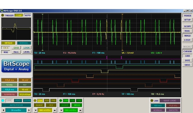
IAW running:
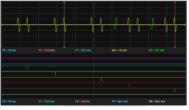
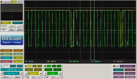
VEMS cranking:
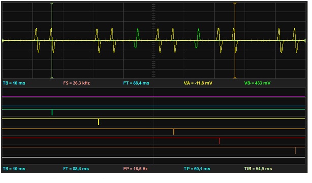
VEMS running
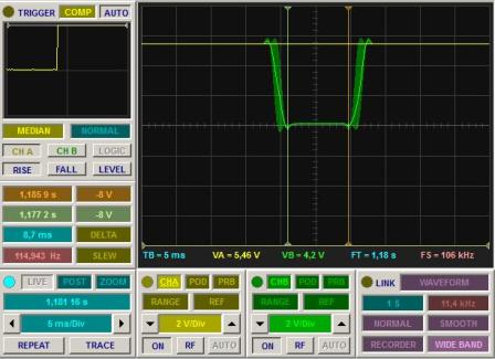
But what about my injectors? one may do crazy things, who knows. So I have scoped each of the engine running. No luck again their voltage traces are about the same. This picture is for cyl4
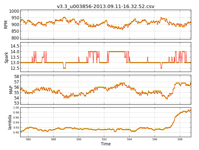
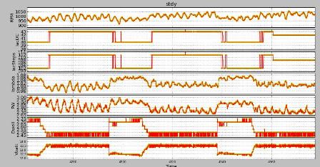
As I have said I feel stupid ... ---- (September 26 2013 _2) fw 1.2.16 tested good so far Yesterday, I tested good on the biturbo (Coil type trigger) fw 1.2.16 for a 20km run. I went up to 6000rmp and 175 map without any misfires contrary to 1.2.15 2013-08-28 (see above) ---- (September 26 2013 _3) Efficient idle spark control Here some plots to show how well the ignition based idle controller works (idle set point is 920 rpm)
---- (October 3 2013 _1) Acceleration enrichment a) start up No success to start on a 1/4 of turn as good as the oem IAW ecu does, the ignition being in both cases Vems. Enrichment during the cranking phase hard do set -b) IAC-DC I have not yet understand the reason for such a difference between oem IAW and Vems. Possibly the surge of the transient in both cases are slightly different which makes the mean positions of the moving shutter slightly off as well In any case there is a bypass screw on the throttle I can adjust -c) Idling w/o AC I did my best to build a dead bottom at the idle reference states (rpm,map) to get a naturally stable behavior, but not enough entries (a dedicated VE idle maps ?). Hence I come to test the I action d) Integral term. I have not understood how the I action works when the increase and decrease limits are both set opened. I done some tests on bench and on the car. As a result, the I total as shown by VT happens to stick to zero @ 2000rpm idle ;). As said elsewhere better to open only the decrease limit and to choose the IAC DC reference for an idle rpm well above the rpm idle target. In this case the integrator term simply starts to add up (for decreasing IAC DC) when the rpm first crosses, from under to above, the rpm idle target. e) Idling AC on This is a concern, (yes the genuine AC on this 1987 my car is working). When switched on, rpm goes down to 600-700, engine still running well, and the battery to 11.6V since the alternator gives no current at this speed. On the IAW there is a signal from the compressor which let the good old 6804 processor of the IAW to compensate for the new charge ;). I have to check for greater I term. d)VE for steady drive My python program can analyze all my records with the different settings and relate VE(RPM,MAP) and lambda(RPM,MAP). I do not understand the reasons to get such large lambda standard deviation as for 0.03. The variation of MAT does not explain it.
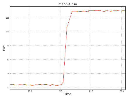
Speed Density equation probably not enough even with MAT compensation. May be have a look about the TP factor. e) acceleration enrichment. I choose "Throttle rule". I have checked previously the time lag induced by the MAP filter against a step input. There are 2 parameters for this filter. Result for (0,1)(first,second)
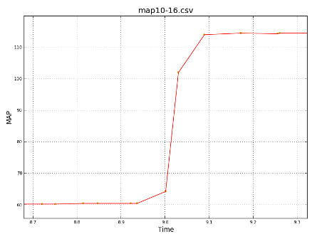
The quantization noise has an amplitude of 1kPa Result for (10,16)
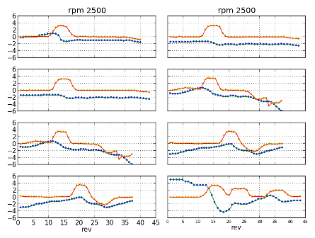
With these parameters noise is gone and one does not see much lag on the step. With (2,10) the amplitude noise is 0.5kPa. Anyhow the noise on the RPM value is of such level that the 1 kPa noise on MAP is without importance. I have done many plots for the effect of the enrichment * W/O Enrichment
Th plots are done against the engine revolutions (720° crank). The tpsDOT is recomputed and lightly filter, its scale may be wrong. Anyway one sees lambda becoming lean when opening the throttle * With enrichment: Fadeout time=0.48 s, Enrichment 10 %
or
I modified the program in order to catch each acceleration for certain rpm,map, and tpsDOT values. There tpsDOT is % of TP per revolution. lambda scale is 30*lambda-30. * Fadeout time=0.86 s, Enrichment 10 %
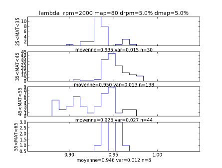
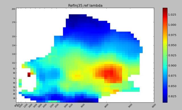
I do not know what is best 0.48s or 0.86s. I would be glad to have hints and recommendation. I have not seen yet the effect of the film parameters. I know the basic that fraction injected will condense to form a liquid fuel film and that the mass of fuel burnt will then change due the evaporation of the condense fuel but I do not know how this relates with these parameters ---- (November 2013) Still tuning injection a) Tuning the VE map I have completed my python program to get this
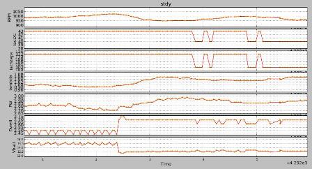
which gives lambda mean local value for steady running whenever the standard deviation is low enough. So i know where to increase or decrease the ve table following the lambda map I wish. Of course, if necessary I need to tune the lambda target map as well. This tool could seem to be a waste of time since VT offers "VE Tune by statistics". Never mind. b) Cranking and idling cold With the cold weather coming on, I needed to tune for cold start and to increase the cranking enrichment curve for low temp much more I first have guessed. It also follows that open loop warm idle get weird because the gearbox oil was cold and offers a bigger resistance, more over the battery went quite low to 9V during the start. * I tried to dig a bottom on the VE map around the (map,rpm) cold and warm states and set an ign retard when TPS=0, * I strengthened the 'ignition idle control' * Finally I added some decreasing and then increasing integral action, and to end, assy. P action. This is to what I came to
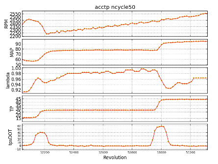
* Suggestions for idle control * two control strategies are involved with quite different time constant: a fast through ignition control and a slow through IACDC. Usually the fast one is done by a an inner close loop and the slow one by an external, but the two has to be kept decoupled (as a turtle and a rabbit can be). So I think the "Threshold For Activating IAC" is counter productive, better to have a standard PID for the ignition loop. - there is a need for a bottom hard barrier (semipermeable) for idle rpm which is set not too far from the target and which insures that rpm would not go below that limit. Indeed there is an asymmetric PID can be enabled which double the PID coef. but this may not be enough. c) PW battery compensation This is what I get when the battery voltage drops by about 0.8V because of the fans start running (I got a small battery)
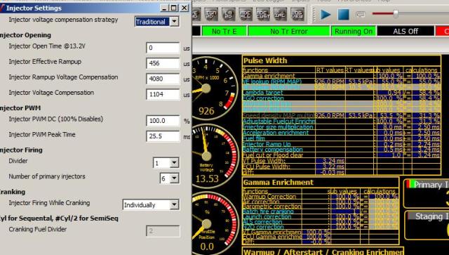
(plots are RPM, IacDC, IntSTEPS, PW, lambda, dwell, battery) Obviously the compensation of the injector timing for that voltage drop is not enough. Alright, I increased the 'Injector Voltage Compensation' parameter from the 'Injector Settings' menu. I follows a slight compensation and the low charge VE value being too rich, which was puzzling. I checked the Pulse Width calc model to quote the Battery compensation value, see hereafter
I was not able to relate the 0.5ms compensation @ 13.53V given by the model with the parameters. Next Vems support explained to me that Battery Compensation = cp*(19-vb/(19-6), where cp is "Injector Voltage Compensation" parameter and vb the actual battery voltage. *Injector Open Time As shown I have put 0 for that parameter, thinking that the open time of the injector is roughly compensated by the close time and neglecting the rise time and the close time of the command signal. Meanwhile I looked for sensible documentation on the subject because most of the info which come out internet is confusing. I got http://www.bosch-motorsport.de/pdf/components/injection_valves/Injection_Valves_en.pdf which gives a curve of the offset time dependency on voltage level and http://www.msextra.com/doc/ms3/injdeadtime.html which gives measurement of effective pulse width duration versus commanded duration. * some rules Alright, I was wrong, closing time do not fully compensate opening time. Depending on the injector type (low, high impedance, old fashion modern) one has a dead time = offset =latency > 0.4ms <0.9ms If it is 0.75 @ 13V one can expect 1.2 @10V, and 1.9 @8V, roughly a 50% increase at each step (non linear). This is probably enough to know. In the case of the Vems calculus cp*(19-vb/(19-6), let cp=1300usec. This gives at 13V , 0.6ms compensation, alright at 10V, 0.9ms compensation too low Conclusion: I shall better be Simple than Traditional |
 .
.
 .
.