Changes by last author:
Added:
|
Trigger setup for Audi S4, 5cyl Direct Fire engine
Audi 2,2T AAN engine * Primary trigger is VR 60-2 multitooth * Secondary trigger is a hall sensor, 10-20 Deg Slot fully adjustable (mockup distributor) * What is the best way to configure this ? ** firmware modification, done in 1.0.25 (seems to work well) * If we set another_trigger_tooth to 12 (5 per crankrot), and extend the h[2] table to 10 cells, and set dummy values every second cell, also for injectors, divider=02. I guess it would work? ** it would work, but with current stable firmware dwell-time would be limited at high RPM. In short, not a good solution. * Config http://linkopingsmotorsport.se/config.txt ** make sure you publish actual config (output of mcd) also, not just the intended config. If you mess up global.h (eg. using an old version, forget to update config.mtt file, whatever) this reveals the truth. * Tables http://linkopingsmotorsport.se/tables.txt * Datalog: http://linkopingsmotorsport.se/datalog200511141121.xls ** if this is sure not captured with primary_trigger=coil-type config (which results in 24x higher RPM than actual, as in the log), than try http://www.vems.hu/files/Firmware/release/v3_firmware_1.0.25.zip we suspect a syntax thingie in 1.0.24 that could result in coil-type being activated 1.0.29 + MT r027 Config http://linkopingsmotorsport.se/config1029.txt Tables http://linkopingsmotorsport.se/tables1029.txt mdd00mdd0clog http://linkopingsmotorsport.se/log.txt 1.0.25 + MT r027 Config http://linkopingsmotorsport.se/config.txt Tables http://linkopingsmotorsport.se/tables.txt Datalog http://linkopingsmotorsport.se/datalog200511281817.xls Datalog http://linkopingsmotorsport.se/datalog200511281819.xls Notice drop in RPM, engine never catches up TODO: * find cases when RPM drops (trigger error), and find out if anything special happens there (like actuation of a misc output) Possible causes * VR waveform shape ** see InputTrigger/RunOut (discussion about waveform updating with this school-example) *** [picture] [wav-file] These explain everything we've seen!
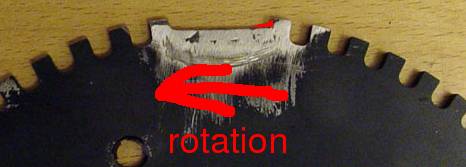
shows Too high amplitude at the missing tooth. Eliminating this would likely help a lot. The first attempt did not help. Unfortunately the welding has different magnetic characteristics, so it's a bit different that if the wheel had been machined that way. You can fill up the small corner-step which leads to the tooth after the gap (considering the rotational direction. before the gap: we don't care):
A [factory wheel] which gives good signal. You can even make the fill (the red part) muuuucccch longer than on the pic, eg. 1.5 tooth long, to span halfway until the gap-mid, don't be afraid of it. The patch you applied seems to have much lower B/H ("magnetivity") than the base material (not the same material, right?). Even if you filled most of the gap with that material, the the pulse would be just a tiny bit smaller than the normal teeth. Do you plan to make this ? Note: no need to mount the wheel on the engine to measure the missing-tooth amplitude. (change the voltage divider 100k/1k to 10k/1k if the notebook sees too low signal) Also, amplitude varies a lot for normal teeth as well, likely because excentric shaft or wheel. Amplitude is bigger where the sensor sees higher "magnetic flux rate of change", eg. because wheel gets closer to the sensor or has higher magnetic permittivity (mu=B/H). Most likely reasons: * distance varies ** very likely! Distance measured: 0.7-0.8mm ** wheel is round and centered. How was this measured ? How big is the gap ?. Smaller gap could also help. * width varies? unlikely. * magnetic characteristics varies? (unlikely) Note: wheel must be mounted on the engine to measure if shaft is centered. TODO: Is the sensor mounting bracket firm ? Yes, made it even stronger but signal is the same The 2 captured waveforms show exactly the same pattern, so it is very unlikely to be caused by vibration (why would the sensor vibrate exactly with the same phase each time?). Possible workarounds Even if the signal remains trash, it might be possible to solve the problem * onboard circuit mod ** use a much higher resistor at LM1815pin7 (R181? not sure). 100k is too small, 180k is usual (you have 180k), use 270k * use reverse VR signal - I'll elaborate on this ** since the pulse amplitude is not so deviant with the reverse polarity, triggering could work. (certainly if applied together with above circuit mod, but could be tried just by itself) ** First I thought that this requires firmware mod, to work with the reverse VR signal, but... ** when thinking about it more, no firmware mod is neccessary, the advanced multitooth trigger filter can be configured to work with the reverse polarity connected 60-2. So (if I'm right), only config change is needed! ** beware that reverse VR means that the processor will see the times of the mid of the gaps, not the mid of the teeth! Adjust ign_tdcdelay accordingly. Normally, the (relative) times for a 60-2 near the missing tooth: * 1 1 3 1 1 with reverse polarity: * 1 1 2 2 1 1 the moving average periods will be * 1 1 1.5 1.75 1.375 1.19 ... This means that the first period=2 will trigger (since >1.5*1) but the second will not (since 2 < 1.5 * 1.5). However, this is a bit too sensitive to rely on. Eg with lengths: * 1 1 1.8 2.2 1 1 1 1 the moving average series: * 1 1 1.4 1.8 1.4 1.2 1.1 1.05 .... Which means the 1.8 will be correctly detected as a missing tooth (since 1.8 > 1.5 * 1) but the second will also, since 2.2 > 1.5*1.4. This is what prevents you to start with reverse polarity. However, with the advanced multitooth trigger you can configure missing-tooth threshold range to be 1.625 (13/8) .. 3.5. * toothrel_normal=0x7A * toothrel_missing=0xB1 * primary_trigger=09 # (instead of 01: bit3=1 enables advanced multitooth trigger) * and don't forget to reverse your VR polarity, so you enjoy the not-so broken signal-peak. * beware that trigger_tooth=0 will not work in this case (scheduling timing from the mid of the missing gap is not good, timing would be slightly uneven!), use min. 1 (maximum is another_trigger_tooth-1) * tooth_wheel=0x3A # this does not change * ign_tdcdelay=0x6a # was 0x64, 3 degrees (half-tooth) add because of reverse polarity VR applied Any luck ? Status as of friday: My mechanic welded as the picture above, didn´t solve the problem but since i have to be at the tyreshop i havn´t been able to make any measurements. Got a new triggerwheel from Holms today (no weld in gap) Will try this during saturday. ---- ECM is unclamped at the moment. (not too easy to measure inside or solder LM1815pin5 jumper for max arming threshold...) ECM: 3.3 #332 "preassembled" This means that you have 180k at the LM1815pin7 (the higher this resistor, the higher tolerance to pulseheight variation, but less tolerant to random noise). ---- |

![[factory wheel]](http://www.vems.hu/files/MembersPage/MarcellGal/EngineSwap/VRsignal/VR_Sensor_Adapter.jpg)