Changes by last author:
Added:
|
For VR sensor
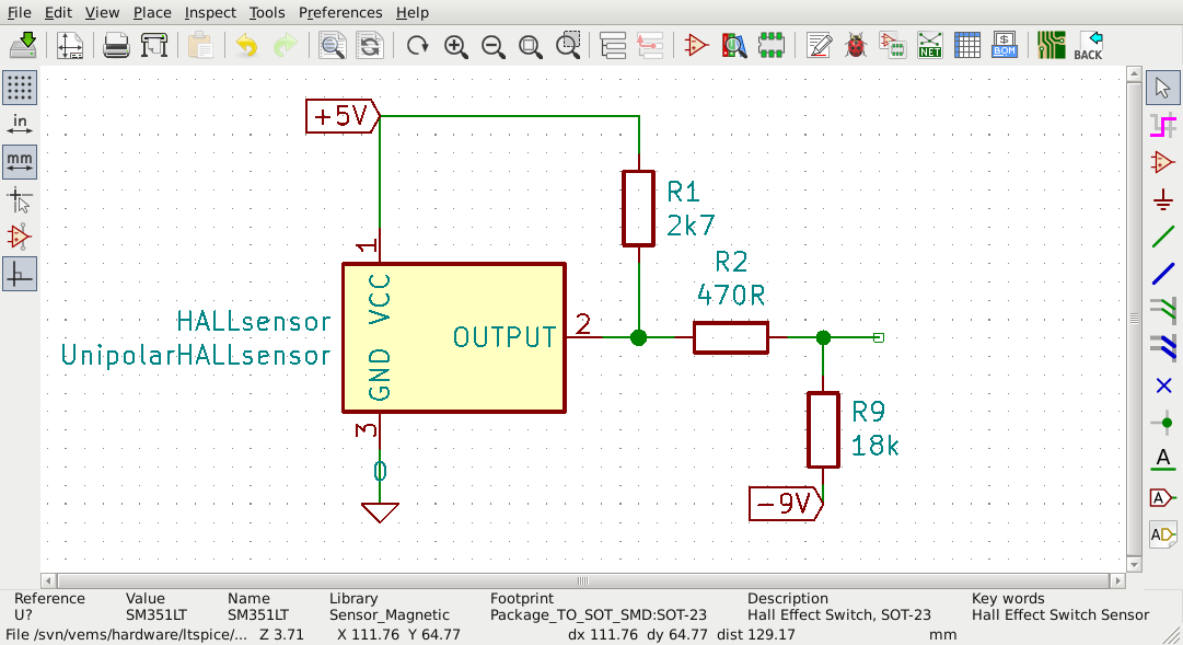
* VR input is needed * or [VR => HALL adapter] and HALL input ---- For HALL sensor, HALL input is needed VR input will normally not work (or worse: might work unreliably) VR input expects the signal to go negative (as a VR sensor...) and HALL sensor signal is positive between 0V (or rather +0.2V in practice) and +4..5V (because of 2k7 pullup resistor to +5V ; this resistor is usually inside the ECU when it has HALL input, otherwise it must be right at the HALL sensor; ) Some trick/hack might be possible (not difficult, but not supported; it might work reliably or not depending on if the installer knows what he is doing ; measuring, scoping, etc... again: not supported) with 470 Ohm and 15..18k resistor divider to get negative signal from mainboard (eg. 15..18k from RS232 -9V available inside on LCD pinheader) theoretically this results in >3V and <-0.01V "square" signal that should be sensed by the VR input, but "your milage may vary"... (again: DISCLAIMER: if it works, fine, but no support for this)
---- Please see [error reporting for Tech help] and create project page via MembersPage * for a VR sensor, measure the resistance of the sensor (measure resistance with DVM with the sensor disconnected from circuit), it should be same in both directions ** In addition to the above, if VR sensor resistance is NOT reported => it is assumed that it might not be a VR sensor, or it might be faulty, or that even the most simple basic measurement is not done (or lacking the cheap tools like DVM or knowledge to use it) => either of them makes technical discussion infeasible (a waste of time). |