Changes by last author:
Deleted:
|
Soldering steps of the mintest:
* o Ohm resistor on the bottom * R154 under the atmega * LCD capacitor (C89) * Big Vbatt capacitor (C72) * Big troughole diode * quartz 16 Mhz * connect the GND-s * pinheaders for the ISP * do the firmware things and checks |
|
Soldering steps after the mintest:
* big black barrell inductivity * knock chip * quartz 4 Mhz |
|
Soldering steps reminder list.
Before mintest * big black barrell inductivity (1.5uH 5.4A or blue 3.3uH 8.8A) * quartz 16MHz |
|
* 0 Ohm resistor on the bottom (D45 for stepper?)
* * * * Big 18V 1.5kE18 troughole transient suppression diode (bottom of the board) (factory populated SMB on top since v3.3, needs checking ! ) * * pinheaders for the ISP * do the firmware things and checks (bin/mintest.sh, bin/prog.pl) Mintest possible at this point * ... * supply voltages * supply current * LCD test requires special connector (since no header) or a bit of experience Optional stuff below * * * configure trigger1 to VR (2 jumpers) * configure trigger2 to HALL (1 jumper) * trigger1 pullup resistor REMOVE (R55) * EC connectors * * flyback airwire (EC36 pin23) * FETs * IGBT * additional brown GND5 airwire on bottom (EC36pin21,pin22) * additional brown GND5 airwire on top (EC36 pin5) * flyback testing: all inj. outputs toward the flyback rail airwires to EC18 * knock * RS232 * MAP signal (if not onboard MAP) * hotmelt Stepper |
| * stepper capacitor (C75) |
| * stepper capacitor (C75) 1210 (min.25V), 10uF |
|
* two trigger zeners (D14, D27)
* trigger1 pullup resistor REMOVE (R55) * configure the trigger1 to VR, and the trigger2 to HALL * flyback diodes * wire out the knock the RS232 and the MAP signals into the EC18 * FETs,IGBT, EC connectors |
| Back to GenBoard/Manual |
|
knock
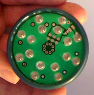
* 4 MHz * TPIC8101DW knock chip for LCD that likes -3V contrast * * Final tests * many * pump- voltage * wbo2_pump_pw_zero * wbo2_nernstdc_target (0.45V between nernst and pump- when WBO2 activated with mde02 or RPM signal) * 64-1 stim-out signal (mstbemsp03) from stepperA (0x36) output, and checking proper operation of all 8 injector and ignition channels with connected LEDs. Requires wasted-spark 16 cyl config with 64-1 wheel ---- A special board is used to test the outputs:
With a * 64-1 stim-signal: mst7e msp02 * tooth_wheel=3e * trigger_tooth=00 * another_trigger_tooth=08 * Note: "coil-type" input-trigger works as well, than the above wheel-parameters are not used, and mst3f msp24 command is used to drive the OutputTrigger * alternate=07 * h[0]=01 02 04 08 10 20 40 80 * ignchmax=07 * h[2]=00 01 02 03 04 05 06 07 it's obvious from first glance if there is any irregularity due to: * firmware problem * HW problem (eg. 2 neighboring IGBT-s shorting because of clamping problem) * config problem (eg. bad trigger configuration or fuelcut) Note that this does not substitute the flyback test. The same board can be used for different tasks, for example: * upper (outer 4 + inner 4=total 8) RED as shiftlight * the other 8 (non-RED, eg. green, blue, yellow and white) LEDs for different status indication: ** fuel-pump active ** variable-intake actuator active ** boost-solenoid active (makes boost-PID tuning easier) ** warmup enrichment active (the output channel for this is not currently configurable) ** finally integral-rail in various PID controllers (idle, boost, WBO2 pump, WBO2 heater, etc...) Note that these indications (although not too complex) are not implemented yet. ** CEL (check engine light) ** add your wish here ** etc... ---- See also |