Changes by last author:
Changed:
| We need to add detailed description of sensors and configuration parameters here. Most can be had from GenBoard/InitialConfig page. |
|
As usual, check in VT help:
[VT help knock configuration] is one of the best step-by-step guide * just follow the steps, do NOT skip (if skipping, on your own: do not complain or ask) * before asking for tech help or support, make sure to have followed the steps, show it explicitely having done so, and also indicate which step seems problematic and why, how (expecting what, measuring what ?) |
| GenBoard/VerThree knockdetection HW |
| If missed to order VEMS ECU with the correct number of knock input - or need some deeper diagnostics: |
|
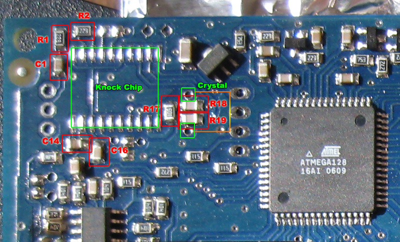
Needed for Knock Sensor input:
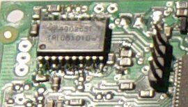
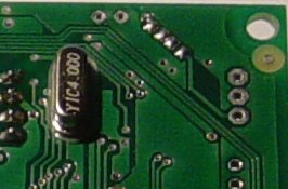
:R1, R2 Knock Channel 1 (10..22k) (analog signal amplitude gain can be adjusted with these; but also in the digital domain - in config) :R3, R4 Knock Channel 2 (same as R1,R2) :R17 1M :C1 Knock Channel 1 (100nF) :C2 Knock Channel 2 (same as C1) :C14 0.22uF :C16 100nF :C18, C19 22pF :Y2 4MHz XTAL (16MHz might work with matching config) :U5 TPIC8101DW (not in rescue kit! Optional, see WebShop) |
|
C17 is no longer used. (was: 2.2nF, can now be left off)
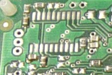
V3.2: if you ordered knock-kit (in same order as genboard) than U5=TPIC8101DW and Y2=crystal already soldered onboard (crystal missing on a few boards sent out before 20041030.) ---- Here you find the top-side components, the second channel uses components on the bottom side too. (thanks to Mr Grogan for pic)
The knock sensor chip installation: Pin 1 points to the connectors-side. (so pin 1 points to the short side of the board)
The crystal goes next to the chip.
For the 2nd channel, the following components are also needed: * 100nF (or 220nF, does not matter which) in the diagonal position * 22k in the diagonal position. As this is in series with the 100nF, they can be swapped: it does NOT matter if the resistor or the cap is closer to the input * 22k (on top side, next to R2) ---- v3.3 The knockchip and 4MHz crystal is installed (if ordered v3.3 with knock-kit), the only thing needed is to connect the sensor input through the 3 pin header (pads) at the northwest corner (looking at the "top") : * North pad (close to board-edge): knockA signal (channel 0) (usually through EC18pin3) * Middle pad: knock GND (usually through EC18pin2) * Southern pad: knockB signal (channel 1) - usually not used TODO: take pictures of board region around knock chip If the knock signal is not routed via EC18, it can be routed through a connector or flying loom cable mounted through frontplate or endplate. |
| See GenBoard/Manual/KnockInput |
|
* Back to GenBoard/Manual/ConnectingSensors
* Back to GenBoard/Manual |
| * GenBoard/Manual/ConnectingSensors |