Changes by last author:
Added:
|
Some v3.6 (or newer) Sectrig=HALL notes (excerpts from GenBoard/Manual/InputTriggerHardWare)
Unsolder SJ7
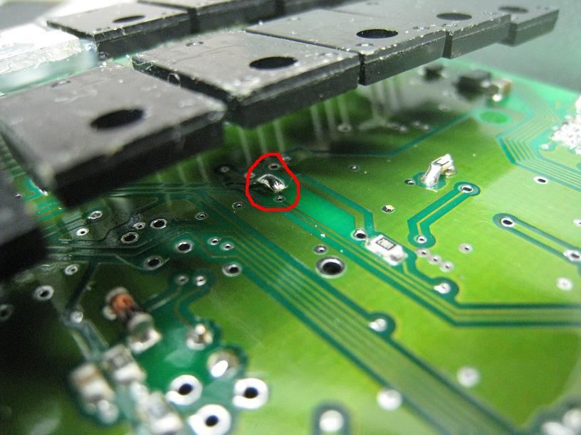
* if you had sectrig=VR or sectrig=auditrigger (and converting to secrig=HALL), than also ** open SJ7 solder-blob on the bottom, so LM1815pin12 output is DISconnected from the microcontroller input pin. This blob is on the bottom, close, to the line of FETs. ** actually this is the only step required if converting from sectrig=auditrigger (because that already has the HALL part of the circuit set up from EC36/13) ----
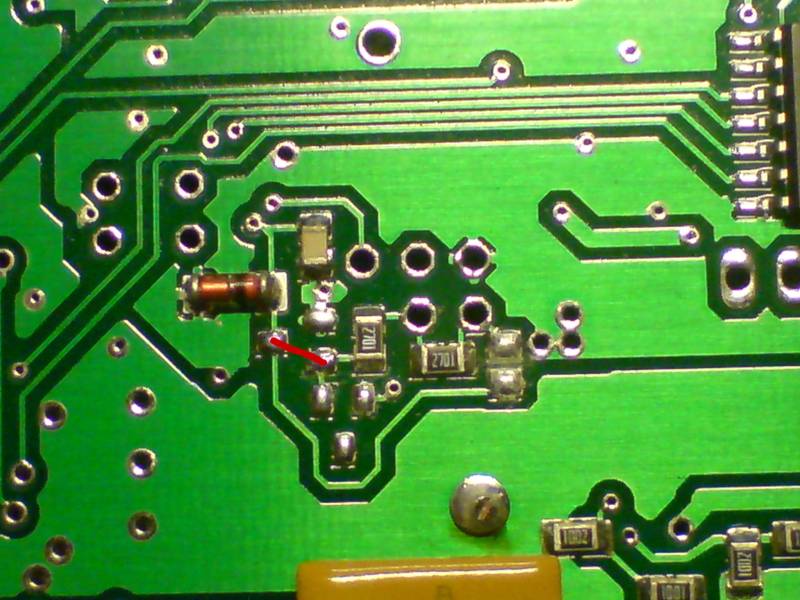
* the instruction says: all 5 throughole pads in the middle must be empty ** note: jumpers are also like wires, might need to reconfigure if they were configured for VR ---- Verification, R48, connecting the right signal to EC36/13 pin * EC36/13 sectrig input pin should be connected to the proper side of R48 (the other side of R48 is +5V) * With input disconnected: Should measure 3.7V or higher (absolute min 3.3V) at EC36/13 (or the CPU side of SJ7) when powered up and input not connected * With a 1kOhm resistor between GND and input (instead of HALL sensor), DC voltage should measure between 0.5V and 1.5V ** eg. 870 mV: voltage divider equation: U=5V * R/(R + Rpullup) ---- Verify in InputTrigger/TriggerLog |