Changes by last author:
Changed:
| Verify and measure every connection before powering up. |
| Verify and measure every connection before powering up. Do NOT underestimate the importance of good grounding. Grounding well is cheap, but if doing sloppily, the learning price is high. |

|
| See MembersPage/PhatBob/UserGuide for ground hints and drawing. |
|
----
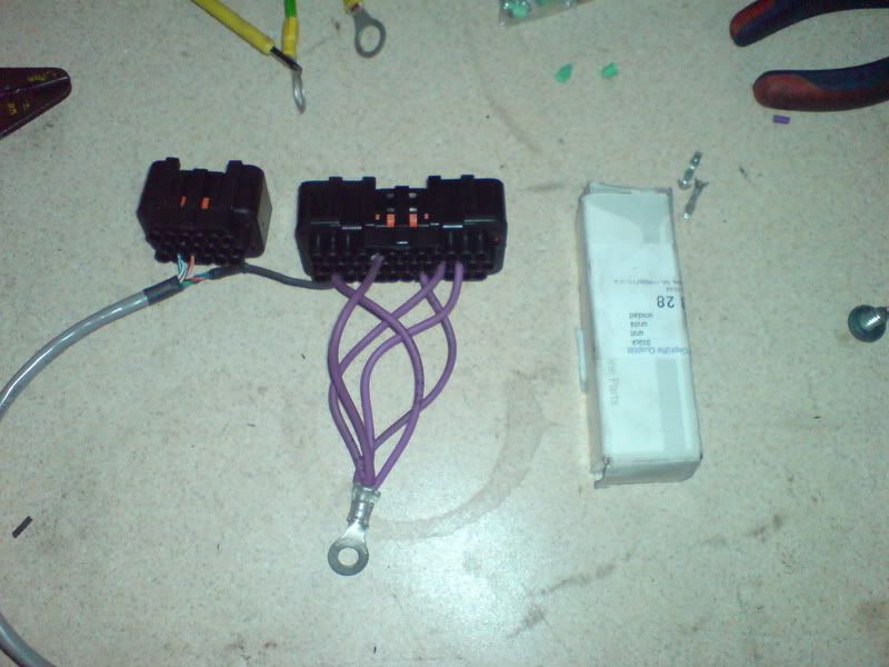
Verification You just arrived to the site. They have the engine wired, and wires wrapped nicely * according to your written instructions (in most cases prefer checklist to drawing) ** that you made after their documented measurements ** that were done according to your measurement-instructions (mostly Ohm-measurement of sensors and injectors) They promise that the wiring perfectly matches the instructions. In general, for their benefit, you better not believe them: They worked helluva lot on the engine, and are very anxious to start and drive it. Your job is to slow them down and only allow the next step when there is reasonable confidence in safety. Most connections can be verified easily, mostly with the Ohm-meter and visual inspection. You should also verify the grounds. The DVM is suitable for this, but not in a simple Ohm-meter mode. You need some higher load, like a 21W (or higher) lightbulb. * disconnect the ECU if it was connected * apply 12V to the lightbulb * the ground of the lightbulb will be pulled down by the power ** this simulates that the outputs are loaded, like if injectors or ignition were drawing current * do each GND5 output (EC36 pins 5,21,22 and 32), and ** measure DC 200mV on the just loaded GND5 with EC36pin26 as base You will see that the loaded GND5 is appr 10..30mV higher than EC36pin26 GND. If the voltage is max 10..16 mV/A, than the ground connections are sufficient. For a 21W lightbulb (14V, 1.5A, 9.3 Ohm when hot) this means that anything higher than 1.5A * 16mV/A = 24mV must be redone, properly. If you measure less than 2mV, check if you measure properly (as that is very unlikely). 2 .. 15mV seems sufficient at this time. Make sure that they are made to last: no loose screws, temporary alligator-clips or other nastiness that could ruin the ground-system. Note that this test only verifies that the GND5 is unlikely to divert dangerously from GND. It will NOT reveal if the trigger-ground is connected to the wrong place (which might inject noise to the trigger signal: mostly problematic with VR-sensor, cold-cranking, especially if the toothcount is 12-1 or less). |
| * MembersPage/PhatBob/UserGuide for ground hints and drawing |