Changes by last author:
Added:
|
ISP via PC Parallel (printer) port
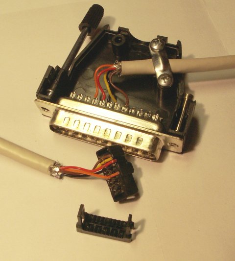
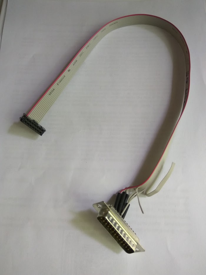
Originally on MembersPage/MattiasSandgren/NickesBMW/AvrBootCode (thanks Mattias). ---- * On XP (or later mswin ?) you may have to install giveIO usually found in c:/winavr/bin/install_giveio.bat to enable direct access to the parallel port. * Command syntax : avrdude -c bsd -p m128 ... ||AVR pin command||ISP header #||Parallel port pin||Notes|| ||AVR /RESET||5||7||Yellow|| ||AVR SCK (clock input)||3||8||Black|| ||AVR PDI (RXD) (instruction in)||4||9||Red|| ||AVR PDO (TXD) (data out)||1||10||Orange|| ||Signal Ground||6||18||Brown|| * MOSI and MISO are not used. Correct pins from the schematics AVR pin 2 = RXD/PDI -> ISP header Pin4, AVR Pin3 = TXD/PDO -> ISP header pin 1 See signal functions vs header pins [bottom: "VEMS V3 ISP pinout"] (also called "ISPI") The avrdude bsd pinout is compatible with the alf pinout (so -c alf should work just as well). The alf code also sets some status (ready, error, verification, complete ...) LEDs that can be useful for fancy geeks (although the same info is also on avrdude screen, and some in return value). This is what it looked like:
---- 330 Ohm recommended on all 4 signal lines (or sg. between 270..348 Ohm for protection) * GND is direct wire of course ** multiple GND could be connected, pin21 on this cable. * Cable length should be 0.4m (1.2 feet) or less. * request "5..10 pieces of throughole 348 Ohm resistors" in WebShop in your order comment (best effort - provided free of charge) or add a few [348 Ohm] to cart.
---- |